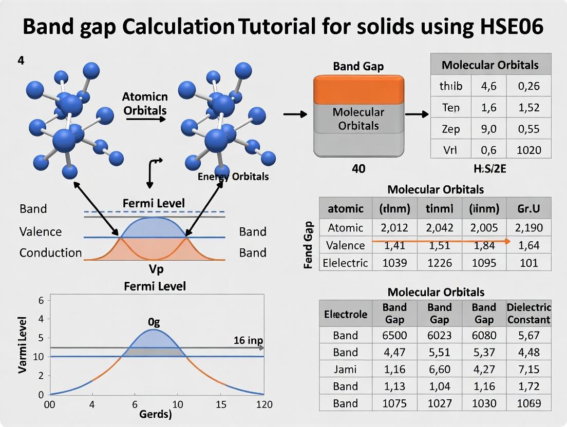
Mastering HSE06 Band Gap Calculations: A Step-by-Step DFT Guide for Pharmaceutical & Materials Researchers
This comprehensive tutorial provides researchers, scientists, and drug development professionals with a practical guide to performing accurate HSE06 hybrid functional band gap calculations for solid-state systems.
Mastering HSE06 Band Gap Calculations: A Step-by-Step DFT Guide for Pharmaceutical & Materials Researchers
Abstract
This comprehensive tutorial provides researchers, scientists, and drug development professionals with a practical guide to performing accurate HSE06 hybrid functional band gap calculations for solid-state systems. We explore the foundational theory behind hybrid functionals and their critical importance in predicting electronic properties, detail a complete methodological workflow from input preparation to analysis, address common convergence and accuracy challenges, and validate results against experimental data and other functionals. The article empowers readers to reliably calculate band gaps for applications in semiconductor design, photovoltaic materials, and drug delivery systems.
Why HSE06? Understanding Hybrid Functionals for Accurate Solid-State Band Gaps
Within the broader thesis on "HSE06 Band Gap Calculation Tutorial for Solids Research," this application note addresses a fundamental challenge: the systematic underestimation of electronic band gaps by standard Density Functional Theory (DFT) functionals, specifically the Local Density Approximation (LDA) and Generalized Gradient Approximation (GGA). This "band gap problem" critically impacts the predictive accuracy for pharmaceuticals (e.g., photoactive drugs, molecular semiconductors) and functional materials (e.g., photovoltaic absorbers, catalysts). This document details the limitations, provides comparative quantitative data, and outlines foundational protocols for researchers transitioning to more accurate hybrid functionals like HSE06.
Quantitative Comparison of Band Gap Accuracy
The following table summarizes the typical percentage error of band gap predictions for various material classes using LDA/GGA compared to experimental values.
Table 1: Band Gap Underestimation by Standard DFT Functionals
| Material Class | Example Material | Experimental Band Gap (eV) | Typical LDA/GGA Result (eV) | Average Underestimation (%) | Critical Impact for Applications |
|---|---|---|---|---|---|
| Elemental Semiconductors | Silicon (Si) | 1.17 | 0.5 - 0.7 | ~45% | Electronic device modeling |
| III-V Semiconductors | Gallium Arsenide (GaAs) | 1.42 | 0.3 - 0.5 | ~70% | Optoelectronics design |
| Oxide Wide-Gap Semiconductors | Zinc Oxide (ZnO) | 3.37 | 0.7 - 1.0 | ~75% | Transparent conductive oxides, sensors |
| Pharmaceutical Molecules | Acridine (model system) | ~4.0 | 2.0 - 2.5 | ~45% | Phototoxicity, singlet fission studies |
| Perovskite Solar Materials | MAPbI₃ | ~1.6 | 0.7 - 1.1 | ~40% | Photovoltaic efficiency prediction |
| 2D Materials | Monolayer MoS₂ | 1.8 - 2.1 (direct) | 1.4 - 1.7 | ~20% | Nanoelectronics, valleytronics |
Data synthesized from current literature (2023-2024).
Root Cause: The DFT Band Gap Problem
The fundamental issue stems from the inherent nature of semilocal LDA and GGA functionals. They lack a derivative discontinuity in the exchange-correlation potential and suffer from self-interaction error. This leads to an imprecise description of the excited-state necessary to calculate the band gap (the difference between the ionization potential and electron affinity). In practice, the Kohn-Sham eigenvalues are erroneously compressed, severely underestimating the gap.
Diagram: Logical Flow of the DFT Band Gap Problem
Title: Root Causes of LDA/GGA Band Gap Underestimation
Protocols for Assessing Functional Limitations
Protocol 4.1: Benchmarking Band Gaps for Pharmaceutical Molecules
Objective: To quantify the error of PBE (GGA) for a set of organic semiconductor/pharmaceutical molecules.
Materials:
- Quantum chemistry software (e.g., VASP, Quantum ESPRESSO, Gaussian)
- Set of 5-10 molecules with experimentally known optical gaps (e.g., Acridine, Tetracene, Perylene).
Procedure:
- Geometry Optimization: Optimize the molecular geometry using the PBE functional and a moderate basis set (e.g., 6-31G* in Gaussian or plane-wave cutoff ~500 eV in VASP). Use a large vacuum space (>15 Å) to prevent periodic image interactions.
- Single-Point Energy Calculation: Perform a single-point calculation on the optimized geometry with the same PBE functional.
- Extract HOMO-LUMO Gap: Extract the Kohn-Sham HOMO and LUMO eigenvalues. The difference is the predicted PBE gap.
- Comparison: Compare the calculated PBE gap with the experimental optical absorption onset (adjusted for exciton binding energy where possible).
- Analysis: Compute the mean absolute error (MAE) across the test set. Expect MAE > 1.5 eV.
Protocol 4.2: Bulk Solid Band Gap Calculation with LDA and GGA
Objective: To compute the band structure of a prototype semiconductor (e.g., Silicon) with LDA and PBE-GGA.
Materials:
- Plane-wave DFT code (e.g., VASP, Quantum ESPRESSO, ABINIT).
- Pseudopotential for the element(s).
- Known experimental lattice constant.
Procedure:
- Structure Input: Build the crystal structure file (e.g., POSCAR) using the experimental lattice constant.
- SCF Calculation: Perform a self-consistent field (SCF) calculation with high accuracy (energy convergence < 1e-6 eV/atom) using LDA (e.g., CA-PZ) and PBE pseudopotentials. Use a k-point mesh of at least 8x8x8 for Si.
- Non-SCF Band Structure Run: Using the converged charge density, perform a non-self-consistent calculation along a high-symmetry k-path (e.g., Γ-X-W-K-Γ for FCC).
- Data Extraction: Extract the valence band maximum (VBM) and conduction band minimum (CBM) energies from the band structure data.
- Gap Calculation: Calculate the indirect/direct gap. For Si (indirect), find the VBM at Γ and the CBM near X.
- Documentation: Record the LDA and PBE gaps. Compare with the experimental 1.17 eV gap at 300K.
The Scientist's Toolkit: Essential Research Reagents & Materials
Table 2: Key Computational Reagents for Band Gap Studies
| Item | Function/Description | Example/Note |
|---|---|---|
| Pseudopotential/PAW Dataset | Replaces core electrons, reduces computational cost. Critical for plane-wave codes. | Choose consistent sets (e.g., VASP's PBE or GW versions) for fair comparisons. |
| K-Point Mesh | Samples the Brillouin Zone for integration. Determines accuracy of total energy and eigenvalues. | A 6x6x6 Monkhorst-Pack mesh is often a starting point for cubic crystals. |
| Plane-Wave Cutoff Energy (ECUT) | Determines basis set size for wavefunction expansion. Higher ECUT increases accuracy and cost. | Must be tested for convergence (e.g., energy change < 1 meV/atom). |
| Hybrid Functional (HSE06) | "Reagent" mixing exact HF exchange with PBE. Corrects self-interaction error, improves gaps. | The target method in the overarching thesis. Parameter: 25% HF, screening parameter ω=0.2 Å⁻¹. |
| GW Pseudopotential | Specialized potentials designed for many-body perturbation theory (beyond DFT) calculations. | Used in the GW method, considered the "gold standard" for quasiparticle gaps. |
| Experimental Reference Database | Curated set of reliable experimental band gaps for benchmarking. | Examples: Materials Project, NIST Atomic Spectra DB, organic semiconductor literature. |
Workflow: From Problem Diagnosis to Solution with HSE06
Diagram: Protocol for Diagnosing and Solving the Band Gap Problem
Title: Diagnostic Workflow for Accurate Band Gap Prediction
The Heyd-Scuseria-Ernzerhof (HSE) screened hybrid functional, specifically the HSE06 variant, represents a pivotal advancement in density functional theory (DFT) for the accurate computation of electronic properties in solids. Standard DFT functionals (e.g., LDA, GGA) suffer from the band gap problem, systematically underestimating the band gaps of semiconductors and insulators. HSE06 addresses this by mixing a fraction of exact, non-local Hartree-Fock (HF) exchange with the semi-local PBE exchange-correlation functional, using a screened Coulomb potential to partition the exchange interaction. This approach significantly improves the prediction of band gaps, lattice constants, and reaction energies, making it indispensable for materials science and computational drug development where electronic structure is critical.
Table 1: Comparative Performance of HSE06 vs. Other Functionals for Band Gaps (Selected Solids)
| Material | Experimental Band Gap (eV) | PBE Band Gap (eV) | HSE06 Band Gap (eV) | HSE06 % Error |
|---|---|---|---|---|
| Si | 1.17 | 0.60 | 1.17 | 0.0% |
| GaAs | 1.42 | 0.40 | 1.35 | -4.9% |
| TiO2 (Rutile) | 3.0 | 1.8 | 3.1 | +3.3% |
| ZnO | 3.44 | 0.80 | 2.38 | -30.8% |
| CdS | 2.42 | 1.10 | 2.15 | -11.2% |
Note: HSE06 typically uses 25% exact HF exchange and a screening parameter (ω) of 0.2 Å⁻¹. ZnO's larger error is a known limitation for certain systems.
Application Notes for Band Gap Calculations
Core Parameter Selection
The accuracy of HSE06 hinges on two key parameters: the mixing parameter (α) for exact exchange and the screening parameter (ω). The standard HSE06 uses α = 0.25 and ω = 0.2 Å⁻¹. For systems with strong electron correlation (e.g., transition metal oxides), tuning α between 0.15-0.35 may be necessary. The screening parameter controls the range-separation; a smaller ω increases long-range exact exchange.
Convergence Considerations
Hybrid functional calculations are computationally intensive (10-100x heavier than PBE). Critical convergence parameters include:
- k-point mesh: A denser mesh is required for accurate Brillouin zone integration.
- Plane-wave energy cutoff: Must be increased (~25% higher than PBE) due to the non-local exact exchange operator.
- Integration grids: Finer real-space grids are needed for the exact exchange potential.
Table 2: Recommended Convergence Parameters for HSE06 Calculations (Example: Silicon)
| Parameter | PBE Typical Value | HSE06 Recommended Value | Purpose |
|---|---|---|---|
| Energy Cutoff | 300 eV | 400 - 500 eV | Basis set completeness |
| k-point mesh | 8x8x8 Monkhorst-Pack | 12x12x12 Monkhorst-Pack | Brillouin zone sampling |
| SCF Convergence | 1e-6 eV/atom | 1e-7 eV/atom | Self-consistent field accuracy |
| Total Relative Compute Time | 1x (Baseline) | ~30x | --- |
Experimental Protocol: HSE06 Band Gap Calculation Workflow
Protocol Title: Standard Protocol for Calculating the Electronic Band Structure of a Crystalline Solid Using the HSE06 Functional.
Objective: To determine the fundamental band gap and electronic density of states (DOS) of a semiconductor/insulator material with improved accuracy.
Software: This protocol assumes the use of a common plane-wave DFT code like VASP, Quantum ESPRESSO, or CP2K. Specific instructions may vary.
Materials/Inputs:
- Crystal Structure File: A fully relaxed crystal structure (POSCAR/CIF file) obtained from a PBE geometry optimization.
- Pseudopotentials/PAWs: High-quality, consistent projector-augmented wave (PAW) or norm-conserving pseudopotentials suitable for hybrid calculations.
Procedure:
Step 1: Preliminary PBE Calculation
- Perform a full geometry relaxation (ions + cell volume) using the PBE functional until forces are < 0.01 eV/Å.
- Calculate the PBE electronic structure (band gap, DOS) on the relaxed geometry. This serves as a baseline.
Step 2: HSE06 Single-Point Energy Calculation
- Input File Setup: In the main calculation input file (e.g., INCAR for VASP):
- Set the functional type:
LHFCALC = .TRUE.;HFSCREEN = 0.2;AEXX = 0.25. - Increase computational parameters:
ENCUT = 1.3 * [PBE ENCUT]; set a denseKPOINTSmesh. - Set stringent convergence:
EDIFF = 1E-7.
- Set the functional type:
- Run the HSE06 calculation on the PBE-relaxed structure. Note: Full HSE06 relaxation is often prohibitive.
Step 3: Band Structure and DOS Calculation
- Using the converged HSE06 charge density, perform a non-self-consistent field (NSCF) calculation along high-symmetry k-point paths (for band structure) and on a dense k-mesh (for DOS).
- Extract the band energies and DOS. The fundamental band gap is identified as the difference between the lowest conduction band minimum (CBM) and the highest valence band maximum (VBM).
Step 4: Analysis and Validation
- Plot the band structure and DOS.
- Compare the HSE06 band gap with the PBE result and experimental literature values.
- If the error is systematic (e.g., consistently high/low), consider parameter tuning (see Application Note 2.1).
Title: HSE06 Band Gap Calculation Protocol Workflow
Title: Logical Flow of HSE06 Functional Theory
The Scientist's Toolkit: Essential Research Reagent Solutions
Table 3: Key Computational "Reagents" for HSE06 Calculations
| Item/Category | Function & Explanation |
|---|---|
| High-Performance Computing (HPC) Cluster | Essential hardware. HSE06 calculations are computationally demanding, requiring many CPU cores and significant memory for parallel execution over k-points and bands. |
| DFT Software with Hybrid Support | Primary tool. Software like VASP, Quantum ESPRESSO, or CP2K must be compiled with and licensed for the non-local exact exchange algorithms required by HSE. |
| Optimized Pseudopotential/PAW Libraries | Atomic data. High-quality, consistent sets of pseudopotentials (e.g., from PSlibrary or the VASP PAW library) are needed to accurately represent core electrons and ensure transferability in hybrid calculations. |
| Convergence Test Scripts (Python/Bash) | Automation & validation. Custom scripts to systematically vary parameters (ENCUT, k-mesh) and analyze convergence in total energy and band gap are crucial for reliable results. |
| Visualization & Analysis Suite | Data interpretation. Tools like VESTA (structure), p4vasp, VASPKIT, or Sumo are used to plot band structures, DOS, and electron densities from the raw output files. |
| Reference Experimental Database | Validation. Curated databases (e.g., Materials Project, NIST) provide experimental band gaps and lattice constants for benchmarking and assessing calculation accuracy. |
Within the broader tutorial on HSE06 hybrid functional calculations for accurate band gap predictions in solids, the precise definition of two key parameters—the mixing parameter (α) and the screening range (ω)—is paramount. The HSE06 functional, a cornerstone of modern computational materials science and drug development (e.g., for studying pharmaceutical cocrystals or inorganic carriers), corrects the well-known band gap underestimation of standard DFT by mixing a portion of exact Hartree-Fock exchange. This mixing is screened in real space to improve computational efficiency for solids. The accurate determination of these parameters is critical for obtaining reliable and reproducible electronic structure data.
Theoretical Foundation and Parameter Definitions
Mixing Parameter (α): This defines the fraction of short-range exact Hartree-Fock exchange incorporated into the hybrid functional. In the standard HSE06 functional, α is fixed at 0.25, indicating that 25% of short-range exchange is exact, while 75% is from the PBE generalized gradient approximation (GGA).
Screening Parameter (ω): This inverse length scale (in Å⁻¹) determines the range separation in the error function complement (erfc) operator. It defines the distance over which the exact exchange interaction is screened. The standard value for HSE06 is ω = 0.207 Å⁻¹ (equivalent to 0.11 bohr⁻¹), which corresponds to a screening length of approximately 4.8 Å.
Standard HSE06 Parameterization Table
| Parameter | Symbol | Standard HSE06 Value | Role in Functional |
|---|---|---|---|
| Mixing Parameter | α | 0.25 | Fraction of short-range exact exchange |
| Screening Range | ω | 0.207 Å⁻¹ (0.11 bohr⁻¹) | Defines the range separation/screening length |
Application Notes: Impact on Band Gap Calculations
The choice of α and ω directly influences the calculated electronic band gap (E_g). Systematic studies show:
- Increasing α generally increases the calculated band gap linearly, as more exact, non-local exchange is included.
- Increasing ω increases the calculated band gap. A larger ω means a shorter screening length, causing more exchange to be treated as "short-range" and thus subject to mixing with exact HF exchange.
Band Gap Sensitivity Table (Representative Data)
| Material (Example) | PBE Gap (eV) | HSE06 (Std) Gap (eV) | α=0.30, ω=0.207 (eV) | α=0.25, ω=0.30 (eV) | Experimental Gap (eV) |
|---|---|---|---|---|---|
| Silicon | 0.6 | 1.2 | 1.4 | 1.3 | 1.17 |
| TiO₂ (Anatase) | 2.2 | 3.4 | 3.7 | 3.6 | 3.4 |
| ZnO | 0.8 | 2.4 | 2.7 | 2.6 | 3.4 |
Note: These values are illustrative. Accurate parameter tuning requires matching known experimental or high-level theoretical benchmarks for the specific material class.
Experimental Protocols for Parameter Determination and Validation
Protocol 1: Benchmarking α and ω for a New Material System
Objective: To determine an optimized (α, ω) pair for a novel solid material where standard HSE06 may not yield sufficient accuracy.
Materials & Computational Setup:
- High-performance computing cluster.
- DFT code with HSE-type functional capability (VASP, Quantum ESPRESSO, CP2K).
- Optimized PBE pseudopotentials/plane-wave cutoff.
Methodology:
- Structure Optimization: Fully relax the unit cell geometry using the PBE functional.
- Initial HSE06 Scan: Perform single-point band structure calculations with the standard HSE06 (α=0.25, ω=0.207) to establish a baseline.
- Parameter Grid Construction: Define a 2D grid of parameter values (e.g., α ∈ [0.15, 0.35] in steps of 0.05; ω ∈ [0.15, 0.30] Å⁻¹ in steps of 0.03).
- Band Gap Calculation Grid: For each (α, ω) pair, perform a static calculation and extract the fundamental band gap.
- Benchmarking: Compare calculated gaps against a trusted benchmark (experimental gap from reliable literature or high-level GW calculation).
- Error Minimization: Identify the (α, ω) pair that minimizes the absolute error relative to the benchmark. Plot the error as a contour map.
Validation: The optimized parameters should predict band edges of defect levels or adsorption energies consistent with dedicated experiments.
Protocol 2: Standard HSE06 Calculation for Reproducible Research
Objective: To perform a reproducible band structure calculation for a crystalline solid using the community-standard HSE06 parameters.
Workflow:
Diagram Title: Standard HSE06 Band Gap Workflow
The Scientist's Toolkit: Research Reagent Solutions
Table: Essential Computational "Reagents" for HSE06 Calculations
| Item / "Reagent" | Function & Specification |
|---|---|
| Projector-Augmented Wave (PAW) Pseudopotentials | Core electron potentials. Must be consistent: use the "standard" or "GW" grade PBE potentials provided by the code repository for accurate valence electron description. |
| Plane-Wave Energy Cutoff (ENCUT) | Basis set size. Must be converged (typically 1.3x the maximum cutoff in the POTCAR file for HSE). A key "reagent" concentration affecting accuracy/cost. |
| k-point Mesh (Monkhorst-Pack) | Brillouin zone sampling density. Requires convergence testing. A denser mesh is crucial for accurate metals and defective systems. |
| Hybrid Functional Code | The "reactor" software. VASP (PREC=Accurate, ALGO=All, LHFCALC=.TRUE.), Quantum ESPRESSO (input_dft='hse'), or CP2K (HYBRID section). |
| High-Performance Computing (HPC) Resources | Hybrid calculations are computationally intensive (100-1000x PBE). Adequate CPU cores, memory, and queue time are essential "infrastructure." |
| Benchmark Data | Experimental band gaps from reliable optical absorption/photoemission or high-level ab initio GW results for validation. The "reference standard." |
Within the broader thesis on HSE06 band gap calculation tutorials for solids research, the selection of an appropriate exchange-correlation functional is a critical decision that balances computational cost against the required accuracy. For researchers and scientists, particularly in materials discovery and drug development (e.g., for studying solid-state pharmaceutical forms), understanding the trade-offs between hybrid functionals like HSE06 and PBE0 is essential for efficient and reliable electronic structure calculations.
Key Functional Characteristics and Trade-offs
The following table summarizes the core characteristics, performance, and cost of common functionals relevant to solid-state calculations.
Table 1: Comparison of Key Density Functionals for Solid-State Calculations
| Functional | Type | Key Formulation Adjustment | Typical Band Gap Accuracy (vs. Exp.) | Computational Cost (Relative to PBE) | Best Use Case |
|---|---|---|---|---|---|
| PBE | GGA | - | Underestimates by 30-50% | 1x (Baseline) | High-throughput screening, structural relaxation, large systems. |
| PBE0 | Global Hybrid | 25% Hartree-Fock (HF) exchange mixed globally. | Overestimates for many solids; good for molecules. | ~100-1000x | Molecular systems, organic crystals, where high accuracy for small systems is needed. |
| HSE06 | Range-Separated Hybrid | Screens HF exchange: 25% short-range, 0% long-range. | Excellent for most semiconductors and insulators (error ~10-15%). | ~10-100x | Accurate band gaps of periodic solids, defect levels, moderate-sized supercells. |
| SCAN | Meta-GGA | Uses kinetic energy density. | Better than PBE, but often still underestimates. | ~3-10x | Balanced properties (structure, energy) without hybrid cost. |
Decision Protocol: When to Choose HSE06
Based on current literature and practice, the following workflow outlines the decision-making process for functional selection in solids research.
Title: Functional Selection Workflow for Solids
Experimental Protocol: HSE06 Band Gap Calculation for a Semiconductor
This protocol details a step-by-step methodology for obtaining an accurate band gap using the HSE06 functional, as commonly implemented in codes like VASP.
Protocol 1: HSE06 Single-Point Band Structure Calculation
1. Prerequisite: PBE Structural Optimization
- Objective: Obtain a fully relaxed crystal structure.
- Steps:
a. Build the POSCAR file with an initial guess for the unit cell.
b. Set
ICHARG = 2andISIF = 3in INCAR for full relaxation. c. Use a PBE pseudopotential and a medium precision (PREC = Medium) K-point grid. d. Run the geometry optimization until forces are below 0.01 eV/Å and energies are converged. e. Output: Fully relaxed CONTCAR (rename to POSCAR for next step).
2. HSE06 Self-Consistent Field (SCF) Calculation on High-Symmetry Points
- Objective: Obtain a converged charge density and Fermi energy with HSE06.
- Steps: a. Use the relaxed POSCAR from Step 1. b. In INCAR, set: c. Use a KPOINTS file with a Gamma-centered grid (e.g., 4x4x4 for a semiconductor). The grid must be denser than the PBE calculation due to the hybrid functional's sharper features. d. Run the calculation to convergence. Note: This is the most computationally expensive step. e. Output: CHGCAR, vasprun.xml, OUTCAR.
3. Non-SCF Band Structure Calculation Along High-Symmetry Path
- Objective: Calculate eigenvalues along a specific k-point path to plot the band structure.
- Steps:
a. Keep all files from Step 2.
b. Set
ICHARG = 11in INCAR to read the previously converged charge density. c. SetLWAVE = .FALSE.to avoid writing large WAVECARs. d. Create a KPOINTS file in "line mode" specifying the high-symmetry path (e.g., Γ-X-M-Γ). e. Run the non-SCF calculation. This step is relatively fast. f. Output: vasprun.xml containing eigenvalues along the path.
4. Data Analysis and Band Gap Extraction
- Objective: Determine the direct or indirect band gap.
- Steps:
a. Use a tool (e.g.,
pymatgen,vaspkit, or custom script) to parse the vasprun.xml from Step 3. b. Generate a band structure plot. Identify the valence band maximum (VBM) and conduction band minimum (CBM). c. Note the k-point locations of the VBM and CBM. If they coincide, the gap is direct; otherwise, it is indirect. d. Calculate: Band Gap = CBM Energy - VBM Energy.
The Scientist's Toolkit: Key Research Reagent Solutions
Table 2: Essential Computational Materials for HSE06 Calculations
| Item/Reagent | Function & Explanation |
|---|---|
| High-Performance Computing (HPC) Cluster | Essential for hybrid functional calculations. HSE06 requires significant CPU/GPU resources and parallel computing capabilities. |
| DFT Software (VASP, Quantum ESPRESSO, CP2K) | The primary engine. Must support range-separated hybrid functionals. VASP is most common for solids. |
| Optimized Pseudopotentials (PAW, HGH) | Projector Augmented-Wave (PAW) potentials are standard. Must be consistent with the functional (use HSE06-specific pots if available). |
| Structure Visualization/Modeling Tool (VESTA, ASE) | For creating, manipulating, and visualizing crystal structures (POSCAR files) and charge densities. |
| Post-Processing & Analysis Suite (pymatgen, vaspkit) | Python libraries or standalone codes for automated parsing of output files, calculating band gaps, densities of states, and generating publication-quality plots. |
| Convergence Test Scripts | Custom or community scripts to systematically test k-point mesh density, plane-wave cutoff energy, and HF screening parameter for new materials. |
Accurate electronic band gap determination is critical in materials science and drug development, particularly for photocatalysts, photovoltaic materials, and semiconductor-based sensors. Within Density Functional Theory (DFT), the standard Generalized Gradient Approximation (GGA) functionals notoriously underestimate band gaps. The Heyd-Scuseria-Ernzerhof hybrid functional (HSE06) mixes a portion of exact Hartree-Fock exchange with the GGA exchange-correlation functional, providing significantly more accurate band gaps for solids. However, the computational cost of HSE06 is high, making the careful selection of computational parameters—specifically k-point sampling, plane-wave energy cutoffs, and pseudopotentials—essential for achieving reliable results without prohibitive computational expense.
Core Concepts: Definitions and Quantitative Guidelines
K-Point Sampling
K-points are sampling points within the first Brillouin zone of the reciprocal lattice. Adequate sampling is required to accurately approximate integrals over wavevectors for calculating electronic properties.
Table 1: Recommended K-point Spacing for HSE06 Calculations
| Material Type | Recommended K-point Grid (Γ-centered) | Approximate Spacing (Å⁻¹) | Rationale |
|---|---|---|---|
| Large-gap Insulators (e.g., MgO) | 4x4x4 to 6x6x6 | 0.04 - 0.06 | Slower variation of wavefunctions; coarser sampling sufficient. |
| Semiconductors (e.g., Si, GaAs) | 6x6x6 to 8x8x8 | 0.03 - 0.04 | Requires finer sampling for accurate conduction/valence band extrema. |
| Metals (for DOS) | 8x8x8 to 12x12x12 | 0.02 - 0.03 | Very fine sampling needed to capture Fermi surface details. |
| 2D Materials / Surfaces | Dense in-plane (e.g., 12x12x1), sparse in vacuum direction | 0.02-0.03 in-plane | Accounts for anisotropic electronic structure. |
Protocol 2.1: Converging K-points for HSE06 Band Gaps
- Initial Setup: Start with a primitive cell and a moderate plane-wave cutoff (see Section 2.2).
- Scaling Series: Perform a series of single-point HSE06 calculations using increasingly dense k-point grids (e.g., 2x2x2, 4x4x4, 6x6x6, 8x8x8).
- Monitoring Parameter: Plot the computed band gap (or total energy) against the inverse of the k-point grid density.
- Convergence Criterion: The k-point grid is considered converged when the band gap changes by less than 0.01 eV between successive denser grids.
- Symmetry Consideration: Always use a grid that respects the crystal symmetry. Modern codes automatically generate irreducible k-points from the input grid.
Plane-Wave Energy Cutoff (ENCUT)
The plane-wave basis set expands the electronic wavefunctions. The cutoff energy (ENCUT) determines the maximum kinetic energy of the included plane waves, controlling the basis set size and accuracy.
Table 2: Plane-Wave Cutoff Guidelines for Common Pseudopotentials
| Pseudopotential Type | Typical Recommended Cutoff (eV) | Cutoff for Accurate Stress/Pressure (eV) | Key Elements |
|---|---|---|---|
| Standard Projector-Augmented Wave (PAW) - "Normal" precision | 400 - 500 eV | 600 eV or higher | C, Si, Ge, O |
| "Soft" PAW | 250 - 350 eV | 400 - 500 eV | Na, K, Cs, I |
| "Hard" PAW / High-Precision | 700 - 800 eV | 1000 eV or higher | O (in oxides), N, first-row transition metals |
| Ultrasoft (US) Pseudopotentials | 25-50% lower than equivalent PAW | Similar increase required | Often used for Cu, Pt, Au |
Protocol 2.2: Determining the Plane-Wave Cutoff
- Pseudopotential Specification: Identify the recommended cutoff (
ENMAX) from the pseudopotential file. This is the minimum starting point. - Energy Convergence Test: Using the converged k-point grid, perform a series of calculations on the equilibrium structure, increasing ENCUT in steps of 50-100 eV from the
ENMAXvalue. - Monitoring Parameter: Plot the total energy of the system versus ENCUT.
- Convergence Criterion: The cutoff is converged when the total energy change is < 1 meV/atom. For HSE06, it is advisable to use an ENCUT value that is 1.2 to 1.3 times the maximum
ENMAXamong all element pseudopotentials used. - Note on Stress: For geometry optimizations or molecular dynamics, converge the cutoff with respect to stress/pressure, not just total energy.
Pseudopotentials (PPs)
Pseudopotentials approximate the strong Coulomb potential and tightly bound core electrons, allowing valence electrons to be treated with a plane-wave basis.
Table 3: Pseudopotential Selection for HSE06 Calculations
| PP Type | Description | Pros for HSE06 | Cons | Suitable For |
|---|---|---|---|---|
| Projector-Augmented Wave (PAW) | Frozen core, preserves full charge density near nucleus. | High accuracy, transferable, standard for solids. | Larger basis set than USPPs. | Recommended default for most HSE06 solid-state calculations. |
| Ultrasoft (USPP) | Further smoothens valence wavefunctions. | Lower cutoff, faster computations. | Less accurate for high-electron density regions. | Large systems with heavy elements where PAW is too costly. |
| Norm-Conserving (NCPP) | Valence wavefunctions match all-electron beyond a core radius. | Historically robust, simple. | Requires very high cutoffs. | Not typically used for HSE06 in solids due to high cost. |
Protocol 2.3: Validating Pseudopotential Choice
- Source Consistency: Use pseudopotentials from the same library/generation scheme (e.g., all from VASP's PAW library, or all from GBRV, or all from PSLibrary) to ensure consistent treatment of exchange-correlation.
- Core State Check: Verify that semicore states (e.g., 3d for Ga, In) are treated as valence if they influence the bands near the Fermi level.
- Transferability Test: For critical elements, compare lattice constants and band gaps from HSE06 calculations using different PP versions (e.g., standard vs. hard) to ensure results are not PP-dependent.
- Reference Benchmark: Whenever possible, compare results (lattice parameter within 1%, band gap within 0.1 eV) with high-quality all-electron or published HSE06 results for a test compound.
Integrated Workflow for Parameter Convergence
Diagram Title: HSE06 Parameter Convergence Workflow
The Scientist's Toolkit: Research Reagent Solutions
Table 4: Essential Computational "Reagents" for HSE06 Solid-State Calculations
| Item / Solution | Function in "Experiment" | Example / Specification |
|---|---|---|
| Pseudopotential Library | Provides the effective ionic potential for each element, defining core/valence separation and accuracy. | VASP PAW PBE 5.4 library, PSLibrary 1.0.0, GBRV USPP library. |
| High-Performance Computing (HPC) Cluster | Provides the computational power required for expensive HSE06 SCF cycles and dense k-point sampling. | Nodes with high-core-count CPUs (AMD EPYC, Intel Xeon) and > 4 GB RAM per core. |
| DFT Software with HSE06 | The primary "instrument" for performing the calculation. | VASP, Quantum ESPRESSO, CP2K, ABINIT (with hybrid support). |
| Convergence Scripting Tool | Automates the series of calculations for parameter convergence. | Python with ASE, Bash shell scripts, specific code's internal toolkits. |
| Post-Processing & Visualization Suite | Extracts, analyzes, and visualizes band structures, density of states, and convergence plots. | VESTA, pymatgen, sumo, XCrySDen, Origin/Gnuplot for graphing. |
Table 5: Best Practices Summary for HSE06 Prerequisites
| Parameter | Primary Goal | Recommended Action | Tolerance for Convergence |
|---|---|---|---|
| K-points | Accurate Brillouin zone integration. | Use Γ-centered grids. Converge band gap to < 0.01 eV. Use symmetry reduction. | ΔE_gap < 0.01 eV |
| Plane-Wave Cutoff | Sufficient basis set for valence electrons. | Set ENCUT = 1.3 * max(ENMAX) from PPs. Converge total energy to < 1 meV/atom. | ΔE_total < 1 meV/atom |
| Pseudopotentials | Correct electron-ion interaction. | Use PAW potentials from a consistent library. Treat relevant semicore states as valence. | ΔE_gap < 0.1 eV vs. benchmark |
| Integrated Workflow | Efficient, reliable calculation setup. | Follow sequential convergence: PPs -> ENCUT -> K-points. Document all parameters. | N/A |
Adherence to these protocols for establishing prerequisite knowledge ensures that subsequent HSE06 band gap calculations are founded on a converged and accurate numerical basis, leading to reliable predictions for materials and drug development research.
Your HSE06 Calculation Workflow: From Input Files to Band Structure Plots
Application Notes
Within the broader workflow of an HSE06 hybrid functional band gap calculation tutorial for solids, the initial geometry optimization using the Perdew-Burke-Ernzerhof (PBE) generalized gradient approximation (GGA) functional is a critical, foundational step. This protocol provides a computationally efficient method to obtain a relaxed, ground-state crystal structure from an initial model, which is a prerequisite for all subsequent electronic property calculations. For researchers and computational chemists in materials science and pharmaceutical development (e.g., for crystal structure prediction of active pharmaceutical ingredients), this step ensures that the electronic structure analysis, including the final HSE06 band gap, is performed on a physically realistic and energetically stable configuration, avoiding artifacts from strained atomic positions.
Rationale for PBE Pre-Optimization: HSE06 calculations are significantly more computationally expensive than GGA calculations. Performing a full relaxation with HSE06 is often prohibitive for most solid-state systems, especially those with large unit cells. The PBE functional, while known to underestimate band gaps, provides a reliable and cost-effective means to optimize lattice parameters and atomic coordinates. The resulting structure is typically sufficiently accurate for the subsequent single-point energy and electronic property calculation using the more precise HSE06 functional.
Protocol: Geometry Optimization Using PBE
Preparation of Input Files
- Structural File: Prepare an initial structure file (e.g., POSCAR for VASP, .cif, or other format compatible with your chosen software) containing the crystallographic unit cell and atomic positions.
- Software-Specific Input Parameters: Create the main calculation input file. The following table summarizes the critical parameters for a standard plane-wave DFT code (e.g., VASP, Quantum ESPRESSO).
Table 1: Key Parameters for PBE Geometry Optimization
| Parameter Category | Specific Parameter | Recommended Setting (Typical Solid) | Purpose/Function |
|---|---|---|---|
| Electronic & Convergence | Functional / INCAR: GGA = PE |
PBE | Specifies the exchange-correlation functional. |
| Plane-wave cutoff energy (ENCUT) | 1.3-1.5 x the maximum ENMAX on the POTCAR file | Balances computational accuracy and cost. | |
| Electronic convergence (EDIFF) | 1E-6 to 1E-8 eV | Sets the stopping criterion for the electronic self-consistent cycle. | |
| k-point Sampling | k-point mesh (KPOINTS) | Monkhorst-Pack grid, density ~ 0.03 Å⁻¹ or higher | Ensures accurate integration over the Brillouin zone. |
| Ionic Relaxation | Optimization algorithm (IBRION) | 2 (Conjugate Gradient) | Method for updating ionic positions. |
| Ionic convergence (EDIFFG) | -0.01 to -0.03 eV/Å (force) | Stops relaxation when forces on all atoms are below this threshold. | |
| Maximum number of ionic steps (NSW) | 60-200 | Prevents runaway calculations. | |
| Other | Precision (PREC) | Accurate | Controls FFT grids and other accuracy settings. |
| Smearing (ISMEAR) | 0 (Gaussian) or 1 (M-P), with a small SIGMA (~0.1) | Aids convergence in metallic and insulating systems. |
Execution of Calculation
- Transfer all input files to the high-performance computing (HPC) cluster.
- Submit the job using the appropriate batch script (e.g., SLURM, PBS).
- Monitor job status via queueing system commands and output file (e.g., OUTCAR, output file) inspection.
Analysis of Results
- Convergence Verification: Confirm that the job completed normally by checking for the word "reached required accuracy" or similar in the output file. Ensure the final energy difference and forces met the
EDIFFandEDIFFGcriteria. - Final Structure Extraction: Locate the final, optimized crystal structure. In VASP, this is typically the last set of coordinates in the CONTCAR file.
- Energy and Volume Tracking: Plot the total energy and cell volume as a function of ionic step (see workflow diagram). The energy should monotonically decrease and plateau.
- Structural Metrics: Compare initial and final lattice parameters and atomic coordinates. Calculate relevant bond lengths and angles to ensure the relaxation is physically sensible.
Table 2: Example Optimization Results for a Hypothetical Semiconductor (e.g., TiO₂ Anatase)
| Metric | Initial Structure | PBE-Optimized Structure | % Change | Notes |
|---|---|---|---|---|
| Lattice a, b (Å) | 3.785 | 3.802 | +0.45% | Typical PBE overestimation ~1% |
| Lattice c (Å) | 9.514 | 9.614 | +1.05% | |
| Cell Volume (ų) | 136.30 | 138.95 | +1.94% | |
| Ti-O Bond Length (Å) | 1.937 | 1.946 | +0.46% | Example of an important bond |
| Total Energy (eV) | -42,156.37 | -42,159.84 | - | Final energy is lower, as expected |
Workflow Diagram
Title: PBE Geometry Optimization Workflow for HSE06 Tutorial
The Scientist's Toolkit
Table 3: Essential Research Reagent Solutions for Computational Protocol
| Item / Software | Function / Purpose |
|---|---|
| VASP (Vienna Ab initio Simulation Package) | A widely used proprietary software suite for performing plane-wave DFT calculations, including structural relaxations. |
| Quantum ESPRESSO | An integrated, open-source suite of computer codes for electronic-structure calculations and materials modeling at the nanoscale. |
| Pseudopotential Library (e.g., PSLibrary, SG15) | A collection of pre-generated pseudopotentials that replace core electrons, drastically reducing computational cost. |
| High-Performance Computing (HPC) Cluster | Essential hardware for performing DFT calculations, which require significant parallel processing power and memory. |
| Visualization Software (VESTA, VMD) | Used to visualize initial and optimized crystal structures, charge densities, and atomic displacements. |
| Bash/Python Scripting | For automating file preparation, job submission, and parsing of output data from calculations. |
| POSCAR/CONTCAR File | The VASP format for input and output crystal structures, containing lattice vectors and atomic positions. |
Application Notes
The HSE06 hybrid functional is a cornerstone of accurate electronic structure calculations for solids, particularly for predicting band gaps. Its implementation in VASP requires careful configuration of the INCAR file. The key parameters—ALGO, TIME, HFSCREEN, and AEXX—control the algorithmic approach, computational stability, and the exact exchange mixing, directly influencing the accuracy, convergence, and computational cost of the calculation. Proper tuning of these parameters is essential for reliable results in materials science and drug development research, where predicting electronic properties can guide the design of semiconductors or photovoltaic materials.
Key Parameters and Protocols
Core Parameter Table
| Parameter | Recommended Value for HSE06 | Function & Rationale |
|---|---|---|
| ALGO | All / Damped |
Specifies the electronic minimization algorithm. All is robust. Damped (with TIME) can be efficient for difficult convergence. |
| TIME | 0.4 |
Critical for ALGO=Damped. Controls the time step for the damped molecular dynamics algorithm. Affects convergence stability. |
| HFSCREEN | 0.2 (or 0.3) |
Screens the exact exchange interaction in HSE06. A value of 0.2 Å⁻¹ defines the standard HSE06 functional. 0.3 is sometimes used for faster calculations. |
| AEXX | 0.25 |
Mixing parameter for exact Hartree-Fock exchange. For HSE06, this is typically set to 0.25 (25%). |
| LHFCALC | .TRUE. |
Master switch to enable hybrid functional calculations. |
| PREC | Accurate |
Ensures accurate evaluation of integrals, especially important for hybrid functionals. |
| ENCUT | Explicitly set (e.g., 1.3*max ENMAX) | Cut-off energy. Should be increased (~20-30%) from PBE values for accurate hybrid calculations. |
| EDIFF | 1E-6 (Tight) |
Convergence criterion for electronic steps. Tighter than standard DFT is recommended. |
| NSW | 0 |
For single-point band gap calculations, ionic relaxation is typically turned off. |
| ISMEAR | 0 (Semiconductor) |
Gaussian smearing. Use 0 for semiconductors/insulators. -5 for Blochl's tetrahedron method. |
| SIGMA | 0.05 |
Small smearing width for accurate total energies. |
Experimental Protocol: Setting Up an HSE06 Band Gap Calculation
Aim: To calculate the electronic band gap of a solid (e.g., TiO₂, Silicon) using the HSE06 hybrid functional in VASP.
Workflow:
- Pre-optimization: Perform a full geometry optimization (ionic positions and cell volume) using the standard PBE functional (
GGA = PE) and a moderateENCUT. Ensure forces are below 0.01 eV/Å. - INCAR Preparation for HSE06:
- Start from the optimized
CONTCAR(renamed toPOSCAR). - Use the
WAVECARandCHGCARfrom the PBE calculation as starting points. - Construct the
INCARfile with the core tags as defined in the table above. - A typical minimal HSE06
INCARblock:
- Start from the optimized
- Execution: Run the VASP calculation. Monitor the
OUTCARfor convergence of the total energy and the exact exchange contribution. - Post-Processing: Extract the band gap from the
OUTCAR(search for "band gap") or generate the band structure using a separate run withICHARG=11to read the HSE06 charge density.
Troubleshooting:
- Poor Convergence: If
ALGO = Allfails, tryALGO = DampedandTIME = 0.4. Gradually reduceTIME(e.g., to 0.2) if instability persists. - High Memory Use: Hybrid functionals are memory-intensive. Ensure sufficient RAM per core.
- Incorrect Gap: Verify
KPOINTSdensity. A single Gamma-point is insufficient. Use a mesh appropriate for the material (e.g., 4x4x4 for a cubic unit cell). Always test k-point convergence.
Visualized Workflow
Title: HSE06 Calculation Protocol and Convergence Decision Tree
The Scientist's Toolkit: Essential Research Reagent Solutions
| Item / "Reagent" | Function in HSE06 Calculations |
|---|---|
| VASP Software Suite | The primary computational engine performing the density functional theory (DFT) calculations with hybrid functionals. |
| High-Performance Computing (HPC) Cluster | Provides the necessary parallel computing resources (CPUs, memory) to execute the computationally intensive HSE06 calculations. |
| PBE-Pseudopotentials (Pre-Step) | Standard generalized gradient approximation (GGA) pseudopotentials used for the initial structural optimization, providing a good starting point for HSE06. |
| HSE06-Optimized Pseudopotentials | Pseudopotentials (e.g., PAW datasets) validated or recommended for use with hybrid functionals, ensuring accurate core-valence interactions. |
| Convergence Test Scripts (Python/Bash) | Custom scripts to automate the systematic testing of ENCUT, KPOINTS, and other parameters to establish a converged setup. |
| Visualization & Analysis Tools (e.g., p4vasp, VESTA, Matplotlib) | Software for analyzing results: inspecting crystal structures, plotting band structures, and visualizing charge densities. |
| Reference Database (e.g., Materials Project) | Provides benchmark experimental and computational band gaps for known materials, essential for validating the HSE06 setup. |
Within the broader thesis on accurate band gap calculation using the HSE06 functional for solids research, the selection of the k-point grid is a critical step. It directly controls the sampling of the Brillouin zone, impacting the convergence and accuracy of key electronic properties like the band gap, total energy, and density of states. This protocol details the methodology for determining a converged k-point grid for hybrid functional (HSE06) calculations, which are computationally intensive but essential for predictive materials science and semiconductor research relevant to drug development (e.g., photopharmacology, biosensor materials).
Core Concepts & Quantitative Benchmarks
The k-point grid density required for convergence depends strongly on the unit cell size and symmetry. Larger cells require sparser grids. The following table summarizes generalized convergence thresholds for HSE06 calculations, derived from recent literature and standard practice.
Table 1: General Convergence Criteria for HSE06 Calculations
| Property | Target Convergence Threshold | Typical Grid Starting Point (for ~10 Å cell) |
|---|---|---|
| Total Energy | < 1 meV/atom | 4 x 4 x 4 (Γ-centered) |
| Band Gap (Eg) | < 0.05 eV | 6 x 6 x 6 (Γ-centered) |
| Fermi Level | < 0.01 eV | 6 x 6 x 6 (Γ-centered) |
Table 2: Example Convergence Data for a Hypothetical Semiconductor (e.g., TiO2 Anatase)
| K-point Grid (Γ-centered) | Total Energy (eV/atom) ΔE | Band Gap (eV) | Computational Time (Relative) |
|---|---|---|---|
| 3 x 3 x 3 | 0.000 (reference) | 3.15 | 1.0 |
| 4 x 4 x 4 | -0.002 | 3.19 | 2.5 |
| 5 x 5 x 5 | -0.003 | 3.21 | 5.8 |
| 6 x 6 x 6 | -0.003 | 3.22 | 11.0 |
| 7 x 7 x 7 | -0.003 | 3.22 | 19.5 |
Note: Data is illustrative. A 6x6x6 grid shows convergence for both energy and band gap.
Experimental Protocol: K-point Convergence Testing
Protocol 3.1: Systematic Convergence Test
Objective: To determine the k-point grid density at which the band gap and total energy are converged within acceptable thresholds for an HSE06 calculation.
Materials & Computational Setup: See "The Scientist's Toolkit" below.
Methodology:
- Initial Structure Optimization: Perform a preliminary geometry relaxation using a standard GGA functional (e.g., PBE) and a moderate, well-converged k-point grid. This ensures the atomic positions are not biased by poor k-sampling.
- Grid Selection: Generate a series of Γ-centered k-point grids of increasing density. For a cubic system, test grids like 2x2x2, 3x3x3, 4x4x4, 5x5x5, 6x6x6. For anisotropic cells, scale grid points inversely with lattice vector lengths (e.g., 6x6x4).
- Single-Point HSE06 Calculations: Using the fully optimized structure from step 1, perform a series of static (non-relaxed) HSE06 calculations, varying only the k-point grid between each calculation. Keep all other parameters (cutoff energy, FFT grids, SCF criteria) identical and stringent.
- Data Collection: Extract for each calculation:
- Total energy per atom.
- Fundamental band gap (direct or indirect).
- Direct band gaps at high-symmetry points (if relevant).
- Computational cost (CPU hours).
- Convergence Analysis: Plot the total energy per atom and band gap as a function of k-point grid density (or total number of k-points). The converged grid is identified when increasing the grid density changes the band gap by less than 0.05 eV and the total energy by less than 1 meV/atom.
- Verification: Perform one final HSE06 calculation with the identified "converged" grid and a finer grid (e.g., one point higher in each direction) to confirm stability.
Protocol 3.2: Special Points for DOS and Band Structure
Objective: To generate accurate density of states (DOS) and band structure plots after the converged grid is found.
- For a smoothed DOS, use a denser grid (often 2x finer) than the energy-converged grid or employ a tetrahedron method with Blöchl corrections if available.
- For band structure plots, generate a high-symmetry path (e.g., using seekpath) and interpolate eigenvalues using the converged ground-state charge density.
Visualized Workflow
Title: K-Point Convergence Testing Workflow for HSE06
The Scientist's Toolkit
Table 3: Essential Research Reagent Solutions for HSE06 K-Point Studies
| Item / Software | Function & Relevance |
|---|---|
| VASP, Quantum ESPRESSO, ABINIT | Primary DFT codes capable of performing hybrid functional (HSE06) calculations. They implement k-point sampling and symmetry reduction. |
| Pseudo-potential Library (e.g., PSlibrary, GBRV) | Set of atomic potentials. Use consistent, high-quality potentials (preferably PAW for VASP) across all tests. |
| seekpath (Python tool) | Generates high-symmetry k-point paths for band structure plots and helps identify conventional cells. |
| VASPKIT, sumo (Python tools) | Automates generation of k-point grids of varying densities and analyzes convergence from output files. |
| High-Performance Computing (HPC) Cluster | Essential for running multiple, costly HSE06 calculations in parallel to obtain convergence data in a reasonable time. |
| Visualization Suite (VESTA, XCrySDen) | Used to visualize crystal structures and confirm symmetry, which informs k-point grid choices. |
Within the broader thesis on HSE06 band gap calculation tutorials for solids research, this section details the critical execution phase. The Heyd-Scuseria-Ernzerhof (HSE06) hybrid functional calculation is performed in two primary stages: a self-consistent field (SCF) cycle to obtain the converged hybrid electronic density, followed by a non-self-consistent (NSCF) band structure calculation. This protocol is designed for researchers, scientists, and materials discovery professionals requiring accurate electronic structure data for applications ranging from photocatalysts to semiconductor-based drug delivery systems.
Core Computational Workflow
SCF Cycle with HSE06 Functional
The SCF cycle aims to find the ground-state electron density and total energy using the HSE06 hybrid functional, which mixes 75% of PBE generalized gradient approximation (GGA) exchange with 25% of screened Fock exchange and 100% PBE correlation.
Detailed Protocol:
- Input Preparation: Begin with a fully relaxed crystal structure (from PBE-GGA). The
INCARfile must contain these critical tags:PREC = AccurateISMEAR = 0(Gaussian smearing for semiconductors/insulators)SIGMA = 0.05(smearing width in eV)ALGO = All(robust algorithm for hybrid calculations)LHFCALC = .TRUE.(switches on hybrid functional)HFSCREEN = 0.2(screening parameter for HSE06, in Å⁻¹)AEXX = 0.25(fraction of exact HF exchange)ENCUT = [Value](Plane-wave cutoff energy, typically 1.3x the maximum ENMAX on POTCAR)EDIFF = 1E-6(SCF energy convergence criterion)
K-Point Grid: Use a Γ-centered k-point mesh (e.g.,
KPOINTSfile) with density equivalent to a minimum of 30 / (real-space length in Å) along each reciprocal vector. A Monkhorst-Pack grid like6x6x6is typical for conventional unit cells.Execution: Run the VASP executable (e.g.,
mpirun -np 64 vasp_std > output.scf). Monitor theOSZICARfile for energy convergence. The calculation is complete when the energy change between steps is <EDIFF.Convergence Check: Verify in the
OUTCAR:Free energy of the ion-electron system (eV)is stable.grep "EDIFF" OUTCARshows the last dE is below the threshold.- The total number of SCF steps (
grepped) should be reasonable (< 80). If not, adjustALGO = DampedorTIME = 0.4.
Band Structure Calculation (NSCF)
Following SCF convergence, a fixed-potential NSCF calculation evaluates eigenvalues along high-symmetry k-path.
Detailed Protocol:
- Generate k-Path: Use a tool like
seekpathto obtain the high-symmetry k-point path for your crystal structure. Prepare aKPOINTSfile in "line-mode" listing the path vertices and the number of points between them.
Modify INCAR:
- Set
ICHARG = 11(read charge density from previous SCF). - Set
NSW = 0(no ionic relaxation). - Keep all HSE06 tags (
LHFCALC,HFSCREEN,AEXX) identical to the SCF run. - Set
LORBIT = 11(to enable projected DOS output if needed). ISMEARandSIGMAcan remain the same; for precise band gaps,ISMEAR = -1(tetrahedron method) may be used.
- Set
Execution: Run VASP (
mpirun -np 64 vasp_std > output.nscf). This step is typically faster than the SCF cycle.Data Extraction: Use
vaspkit(option 211) orpymatgento extract band structure data from theEIGENVALandPROCARfiles for plotting.
Table 1: Key HSE06 Calculation Parameters and Typical Values for Common Semiconductors
| Material System (Example) | SCF K-Point Mesh | ENCUT (eV) | Typical SCF Cycles | Approx. Wall Time (CPU-hrs)* | Direct/Indirect Gap? | Expected Band Gap (eV) Range |
|---|---|---|---|---|---|---|
| Silicon (Si) | 6x6x6 | 350 | 40-60 | 400 | Indirect | 1.1 - 1.2 |
| Anatase TiO₂ | 4x4x4 | 500 | 50-70 | 600 | Indirect | 3.1 - 3.3 |
| Gallium Nitride (GaN) | 6x6x4 | 500 | 45-65 | 550 | Direct | 3.2 - 3.5 |
| ZnO | 6x6x4 | 500 | 50-75 | 650 | Direct | 3.3 - 3.6 |
| MAPbI₃ (Perovskite) | 4x4x4 | 400 | 60-80 | 500 | Direct | 1.6 - 1.8 |
*Time estimate based on a 64-core cluster node. Varies significantly with system size and code efficiency.
Visualized Workflow
Title: HSE06 SCF and Band Structure Calculation Workflow
The Scientist's Toolkit: Research Reagent Solutions
Table 2: Essential Computational Tools for HSE06 Calculations
| Tool/Resource Name | Category | Primary Function in HSE06 Protocol |
|---|---|---|
| VASP (v6.3+) | Software | Core DFT & hybrid functional solver. Requires a license. |
| VASPKIT (v1.4+) | Utility | Automates pre- and post-processing (k-path generation, data extraction). |
| PyMatgen | Library | Python materials analysis; processes VASP outputs, plots band structures. |
| SeekPath | Web Tool | Generates high-symmetry k-point paths for band structure plots. |
| POTCAR Files | Pseudo-potential | Projector-augmented wave (PAW) potentials for each element. Must be consistent. |
| High-Performance Computing (HPC) Cluster | Hardware | Provides necessary parallel CPUs for computationally intensive hybrid SCF cycles. |
| GNUPlot / Matplotlib | Visualization | Software for generating publication-quality band structure plots. |
This protocol details the critical post-processing phase of Hybrid Functional (HSE06) band gap calculations for solids. After a successful VASP (Vienna Ab initio Simulation Package) run, essential electronic structure data is contained within the OUTCAR, vasprun.xml, and DOSCAR files. Proper extraction and analysis of these files are paramount for accurate band gap determination, a key parameter in materials science and semiconductor research for applications ranging from photovoltaics to drug development (e.g., photocatalysis for drug synthesis).
The Scientist's Toolkit: Essential Files & Their Functions
| File Name | Primary Function in Band Gap Analysis | Key Data Contained |
|---|---|---|
| OUTCAR | Human-readable text output of the entire VASP calculation. | Final total energy, convergence metrics, precise eigenvalue list at each k-point, magnetic moments. |
| vasprun.xml | Machine-readable XML-structured output. | Complete calculation data, including projected density of states (DOS), eigenvalues, and structural parameters. Used for automated parsing. |
| DOSCAR | Contains total and site-projected density of states data. | Energy grid, total DOS, integrated DOS, and projected DOS (l-decomposed) for each ion. Critical for DOS plots. |
| EIGENVAL | Contains eigenvalues for each k-point and band. | Band energies at each k-point along the chosen path. Primary source for band structure plots. |
| p4vasp / VESTA | Visualization software. | Used to visualize DOS, band structure, and charge densities. |
| Python (matplotlib, py4vasp) | Scripting and analysis. | Custom parsing, plotting, and quantitative extraction of band edges. |
Detailed Protocol for Band Gap Extraction
Protocol A: Direct Band Gap from OUTCAR (Precision Method)
This method extracts the highest occupied (VBM) and lowest unoccupied (CBM) eigenvalues directly.
- Locate Eigenvalues: In the
OUTCARfile, search for the block following "band No. band energies occupation". - Identify VBM and CBM: For a spin-polarized calculation, analyze spin-up and spin-down channels separately. The VBM is the highest eigenvalue with occupancy ~1.0. The CBM is the lowest eigenvalue with occupancy ~0.0.
- Calculate Band Gap: Band Gap (Eg) = CBM - VBM. A negative value indicates an metallic system.
- Consider k-points: The exact k-point where the VBM and CBM occur must be identified. The global band gap is the minimum difference between any CBM and any VBM across the Brillouin Zone.
Protocol B: Band Gap from DOSCAR (Integrated DOS Method)
This method is robust for systems with indirect band gaps or complex DOS.
- Parse DOSCAR: The first line contains the number of ions and grid points. Skip the next five lines. The subsequent data is:
Energy DOS(total) Integrated DOS DOS(projected)... - Extract Data: Load columns for Energy and Total DOS into plotting/analysis software (e.g., Python).
- Locate Fermi Level (EF): EF is set to 0 eV in VASP calculations by default (check
OUTCARfor "E-fermi"). - Determine Band Edges:
- VBM: The highest energy where DOS > near-zero threshold (e.g., 1e-3 states/eV) below EF.
- CBM: The lowest energy where DOS > near-zero threshold above EF.
- Calculate: Eg = CBM - VBM.
Protocol C: Automated Parsing via vasprun.xml and py4vasp
This is the recommended modern approach for integration into automated workflows.
- Install py4vasp:
pip install py4vasp - Use Python Script:
- Output: This provides direct and indirect band gaps automatically.
Quantitative Data Presentation
Table 1: Exemplar HSE06 Band Gap Results for Benchmark Solids (Theoretical vs. Experimental)
| Material | System Type | HSE06 Calculated Gap (eV) | Experimental Gap (eV) [Ref] | % Error | Key Application Note |
|---|---|---|---|---|---|
| Silicon (Si) | Indirect | 1.17 | 1.12 | +4.5% | HSE06 corrects PBE's zero-gap; excellent for semiconductors. |
| TiO2 (Anatase) | Direct | 3.45 | 3.20 - 3.30 | +6.0% | Critical for photocatalyst design in redox reactions. |
| GaN | Direct | 3.36 | 3.30 | +1.8% | Benchmark for optoelectronic and drug delivery sensor materials. |
| Diamond (C) | Indirect | 5.50 | 5.48 | +0.4% | High-pressure/high-temperature material studies. |
Visualization of Analysis Workflow
Title: Workflow for Extracting Band Gap from VASP Output Files
Title: Protocol for Band Gap Extraction from DOSCAR File
Application Notes
This protocol details the visualization of electronic band structures and density of states (DOS) for solid-state materials, a critical step in validating hybrid functional (HSE06) calculations within computational materials science and drug development research (e.g., for photovoltaic or catalytic materials). Effective visualization confirms calculation accuracy, identifies band gap type (direct/indirect), and elucidates orbital contributions to electronic states.
| Quantitative Data Output from HSE06 Calculation (Example: TiO2 Anatase) | |||
|---|---|---|---|
| Property | Calculated Value (HSE06) | Literature Value (Expt.) | Unit |
| Fundamental Band Gap (Γ-Γ) | 3.50 | 3.20 - 3.40 | eV |
| Indirect Band Gap | 3.45 | ~3.30 | eV |
| Valence Band Maximum (VBM) | 0.00 (reference) | 0.00 | eV |
| Conduction Band Minimum (CBM) | 3.50 | 3.30 | eV |
| Total DOS at Fermi Level | 0.00 | 0.00 | states/eV |
| Lattice Parameter a | 3.81 | 3.78 | Å |
| Key Features in Visualized Electronic Structure | |
|---|---|
| Feature | Interpretation in Materials Design |
| Direct vs. Indirect Gap | Determines optical absorption efficiency; direct gaps are preferable for photovoltaics. |
| Band Width & Dispersion | Indicates charge carrier mobility; broader bands suggest higher mobility. |
| DOS Peak Sharpness | Suggests localized (flat band) or delocalized (dispersed) electronic states. |
| Orbital Projection (pDOS) | Identifies atomic/orbital contributions (e.g., O 2p to VBM, Ti 3d to CBM). |
Experimental Protocols
Protocol 6.1: Visualizing Band Structure & DOS with pymatgen
Objective: Generate publication-quality plots of electronic band structure and density of states from VASP HSE06 output files.
- Environment Setup: Ensure Python environment with
pymatgen(>=2024.x),matplotlib, andnumpyinstalled. - File Preparation: Locate HSE06 calculation outputs:
vasprun.xml(contains DOS and band structure data) andEIGENVAL(alternative band structure source). Confirm calculation convergence (OSZICAR). - Generate Band Structure Plot:
- Generate Combined Band Structure and DOS Plot:
- Data Extraction: Use
bs.get_direct_band_gap()andbs.get_band_gap()to extract gap values programmatically for table inclusion.
Protocol 6.2: Visualizing Charge Density/Orbitals with VESTA
Objective: Visualize real-space charge density (e.g., electron density difference) or specific orbitals from HSE06 calculations.
- File Conversion: Convert VASP output
CHGCARorLOCPOTfiles to a VESTA-compatible format if necessary (.xsf). Use pymatgen:Structure.from_file("CHGCAR").to("filename.xsf"). - Load Structure & Data: Open VESTA. Import the crystal structure file (
POSCARorCONTCAR). Then, useFile>Import Data...to overlay the charge density file (CHGCARor .xsf). - Isosurface Rendering:
- Navigate to
Properties>Isosurfaces. - Click
New, select the imported volumetric data. - Set an appropriate isosurface level (e.g., 0.01 to 0.5 e/ų for electron density difference). Adjust color and transparency.
- Navigate to
- Orbital Visualization (if PROCAR is available): For projected charge density, use pymatgen to generate a
.cubefile for a specific band and k-point before loading into VESTA. - Plotting: Use
Objectspanel to toggle visibility. EmployGraphics>Unit CellandSymmetryoptions for clear presentation. Export as high-resolution bitmap or vector graphic.
The Scientist's Toolkit
| Research Reagent / Essential Material | Function in HSE06 Visualization |
|---|---|
| pymatgen Library | Python library for parsing, analyzing, and visualizing materials data. Core engine for generating band structure and DOS plots. |
| VESTA Software | 3D visualization program for structural models, volumetric data (charge density), and crystal orbitals. |
Converged VASP Outputs (vasprun.xml, EIGENVAL) |
Primary data files containing all electronic structure information from the HSE06 calculation. |
| Matplotlib (Python) | Plotting library used by pymatgen to generate and customize 2D graphs. Enables style adjustments for publication. |
| High-Performance Computing (HPC) Cluster | Required to run the preceding computationally intensive HSE06 calculations that generate the data for visualization. |
Workflow and Relationship Diagrams
Title: Workflow for Visualizing HSE06 Electronic Structure Data
Title: From Data to Insight via Visualization Parameters
This application note is situated within a comprehensive thesis on HSE06 band gap calculations for solids research. It details the specialized application of this advanced electronic structure method to two critical classes of materials: pharmaceutical molecular crystals and inorganic drug delivery carriers. Accurate band gap determination is essential for predicting light-induced degradation of drugs and for engineering carrier systems for photodynamic therapy or triggered release.
Theoretical & Computational Background
The Heyd-Scuseria-Ernzerhof (HSE06) hybrid functional is the standard for obtaining accurate band gaps in solid-state systems within density functional theory (DFT). It mitigates the fundamental band gap underestimation of standard semi-local functionals (e.g., PBE) by incorporating a portion of exact Hartree-Fock exchange. For the systems in focus:
- Drug Crystals: Band gaps predict susceptibility to photo-degradation. A lower gap implies absorption of lower-energy (e.g., visible) light, potentially leading to instability.
- Inorganic Carriers: Band gaps are tuned to control drug adsorption/release profiles and to enable photocatalytic or photothermal therapeutic functions.
Table 1: HSE06-Calculated Band Gaps for Representative Systems
| Material System | Crystal Structure | PBE Band Gap (eV) | HSE06 Band Gap (eV) | Experimental Range (eV) | Key Relevance |
|---|---|---|---|---|---|
| Acetaminophen (Form I) | Monoclinic | 3.2 | 4.8 | 4.5 - 5.0 | Photo-stability assessment |
| Sulfathiazole (Form V) | Orthorhombic | 2.8 | 4.3 | ~4.1 | Predicting degradation pathways |
| Mesoporous SiO₂ | Amorphous (Model) | 5.1 | 8.2 | >8.0 | Carrier inertness design |
| TiO₂ (Anatase) | Tetragonal | 2.2 | 3.4 | 3.2 - 3.4 | Photocatalytic drug release |
| Fe₃O₄ (Magnetite) | Cubic | 0.2 | 2.3 | ~2.1 | Magnetic-thermal carrier |
| ZIF-8 (MOF) | Cubic | 3.5 | 4.9 | 4.7 - 5.1 | Controlled drug encapsulation |
Experimental Protocols
Protocol 1: HSE06 Band Gap Calculation for a Molecular Drug Crystal
This protocol details the steps for calculating the electronic band structure of a pharmaceutical crystal using the HSE06 functional.
1. Initial Structure Acquisition & Preparation
- Obtain the crystal structure (e.g., from the Cambridge Structural Database, CSD). Use a primitive cell for computational efficiency.
- Perform geometry optimization using the PBE functional with a plane-wave basis set (e.g., in VASP, Quantum ESPRESSO). Apply DFT-D3 dispersion corrections for van der Waals interactions critical in molecular crystals.
- Convergence Criteria: Energy cutoff ≥ 520 eV; k-point mesh ensuring spacing < 0.05 Å⁻¹; force convergence < 0.01 eV/Å.
2. Single-Point HSE06 Calculation
- Using the PBE-optimized geometry, perform a single-point energy calculation with the HSE06 functional (typically 25% Hartree-Fock exchange, screening parameter ω = 0.2 Å⁻¹).
- Use a reduced but still dense k-point mesh for the Brillouin zone sampling. A Gamma-centered mesh is often sufficient for insulating molecular crystals.
- Due to high cost, consider using a pre-converged PBE charge density as a starting point (ICHARG = 1 in VASP).
3. Band Structure & Density of States (DOS) Calculation
- Generate a high-symmetry k-path (e.g., using SeeK-path tool).
- Run a non-self-consistent field (NSCF) calculation along this path using the HSE06 Hamiltonian.
- Simultaneously, calculate the total and projected density of states (DOS, PDOS) on a dense, uniform k-point grid to identify orbital contributions (e.g., from API vs. excipient).
4. Analysis
- Extract the band gap from the band structure plot and the DOS.
- Visualize the charge density of the valence band maximum (VBM) and conduction band minimum (CBM) to identify molecular fragments involved in excitations.
Protocol 2: Band Gap Tuning in Inorganic Carriers (Doped TiO₂)
This protocol outlines the methodology for modeling doped inorganic systems to engineer band gaps for targeted drug delivery applications.
1. Supercell Construction & Dopant Placement
- Build a 2x2x2 or larger supercell of the pristine carrier material (e.g., anatase TiO₂, 48 atoms).
- Systematically substitute one host atom with a dopant atom (e.g., Nitrogen for Oxygen, or Niobium for Titanium) to model the desired doping concentration.
- Generate multiple configurations for substitutional doping and select the one with the most symmetric dopant distribution, or average results over configurations.
2. Geometry Optimization of Doped System
- Optimize the doped supercell structure using the PBE+U approach (e.g., +U on Ti 3d states) to better describe correlated electrons. Maintain the same convergence criteria as in Protocol 1.
3. HSE06 Electronic Structure Analysis
- Perform a single-point HSE06 calculation on the optimized doped structure.
- Calculate the band structure and DOS/PDOS, paying particular attention to new mid-gap states introduced by the dopant.
- Analyze the change in the CBM/VBM positions relative to the pristine system and relevant redox potentials (e.g., for reactive oxygen species generation).
Visualizations
HSE06 Workflow for Drug Crystals
Band Gap Engineering via Doping
The Scientist's Toolkit: Key Research Reagent Solutions
Table 2: Essential Computational Materials & Tools
| Item/Category | Function & Relevance in Band Gap Studies |
|---|---|
| HSE06 Hybrid Functional | Provides accurate quasiparticle band gaps, essential for reliability. Parameter: 25% HF exchange. |
| DFT-D3 Correction | Accounts for dispersion forces, critical for correct geometry in molecular crystals and adsorption studies. |
| Projector Augmented-Wave (PAW) Potentials | High-accuracy pseudopotentials for core-valence electron interaction, especially for transition metals in carriers. |
| VASP / Quantum ESPRESSO | Leading software packages for performing periodic DFT calculations with HSE06 capability. |
| VESTA / VMD | Visualization tools for crystal structures, charge density isosurfaces, and orbital localization. |
| pymatgen / ASE | Python libraries for automated workflow management, analysis, and high-throughput screening of materials. |
| Cambridge Structural Database (CSD) | Primary repository for experimental small-molecule and drug crystal structures (input geometry). |
| Materials Project Database | Repository of calculated properties for inorganic compounds, used for validation and carrier selection. |
Solving Convergence Issues & Optimizing HSE06 Calculations for Efficiency
Within a broader thesis on HSE06 band gap calculation tutorials for solids research, error messages in electronic structure calculations present significant hurdles. This note details common errors encountered during HSE06 hybrid functional DFT runs, particularly for solid-state systems, providing researchers and drug development professionals with targeted solutions to ensure reliable computation of electronic properties.
Error Analysis and Solutions
ZHEGV: Diagonalization Failure in SCF
The ZHEGV error signifies a failure in the generalized eigenvalue problem solved during the self-consistent field (SCF) cycle, often due to ill-conditioned overlap matrices or problematic projectors.
Root Causes:
- Poor initial guess or atomic configuration.
- Inaccurate pseudopotentials (PAW datasets) for specific elements.
- Extreme geometrical configurations.
- Numerical noise in the overlap matrix (S) or Hamiltonian (H).
Recommended Solutions:
Improve Initial Guess:
- Use
ICHARG = 2to read the charge density from a previous, simpler (e.g., PBE) calculation. - Perform a few initial SCF cycles with
ALGO = Normalbefore switching to the more efficientALGO = AllorFast.
- Use
Adjust SCF Parameters:
- Increase the SCF convergence criterion (
EDIFF) to 1E-7 or tighter to reduce numerical noise. - Use
ISMEAR = 0(Gaussian smearing) with a small SIGMA (e.g., 0.05) for insulators/semiconductors.
- Increase the SCF convergence criterion (
Algorithmic Changes:
- Add
LREAL = .FALSE.to avoid potential projector issues in real-space projection. - For metallic systems, increase
SIGMA(smearing width) stepwise.
- Add
FEXCP: Fatal Error in Exact Exchange Kernel
The FEXCP error is specific to hybrid functional calculations (like HSE06) and indicates a failure in computing the exact exchange potential, often due to memory or parallelization issues.
Root Causes:
- Insufficient memory for the exchange kernel, especially with many bands or k-points.
- Incompatible parallelization settings (
KPAR,NCORE). - Corrupted or incompatible pseudopotential files for hybrid calculations.
Recommended Solutions:
Memory Management:
- Reduce the number of bands included in the exact exchange calculation by setting
NBANDSexplicitly to the minimum required (typically ~1.2 * number of valence electrons / 2). - Increase the available memory per core or reduce the number of MPI tasks.
- Reduce the number of bands included in the exact exchange calculation by setting
Parallelization Tuning:
- Set
KPAR = 1to distribute k-points over bands first. For large k-point sets, tryKPAR > 1but ensure it divides NKPTS evenly. - Use the
–pexchflag in the VASP makefile for improved hybrid parallelization and experiment withNCORE(typical values: 1-4, matching cores per node).
- Set
System Checks:
- Verify that all PAW pseudopotentials are from the same version and are explicitly recommended for hybrid calculations (often labeled "GW" or "hybrid").
NELM: SCF Convergence Failure
The NELM error occurs when the SCF cycle fails to converge within the maximum number of steps (NELM, default=60). This is a frequent issue in HSE06 due to its more complex, non-local potential.
Root Causes:
- Insufficient k-point sampling.
- System is metallic or has a small band gap.
- Poor charge density mixing.
Recommended Solutions:
Optimize Mixing Parameters:
- Use
IMIX = 4(Pulay mixing) for HSE06. - Gradually reduce the mixing parameter
AMIX(try 0.05 to 0.02) and increaseBMIX(try 0.001 to 0.0001). - For difficult cases, set
AMIX = 0.05,BMIX = 0.0001,AMIX_MAG = 0.8, andBMIX_MAG = 0.0001.
- Use
Staggered Convergence Protocol:
- Converge the system first with a standard GGA (PBE) functional.
- Use the PBE charge density (
ICHARG=1or2) as the starting point for the HSE06 calculation. - Perform an initial HSE06 run with a reduced Hartree-Fock (
HFSCREEN = 0.3) or a coarser k-mesh, then restart with full parameters.
Table 1: Summary of Common Errors, Primary Triggers, and Key Solution Parameters
| Error Code | Primary Trigger (HSE06 Context) | Critical INCAR Parameters to Adjust | Typical Value Range for Solution |
|---|---|---|---|
| ZHEGV | Ill-conditioned overlap matrix at start of SCF. | ALGO, ICHARG, LREAL, ISMEAR, SIGMA |
ALGO=Normal, ICHARG=2, LREAL=.FALSE. |
| FEXCP | Insufficient memory for exact exchange kernel. | NBANDS, KPAR, NCORE |
NBANDS = 1.2*N valence electrons/2, KPAR=1, NCORE=2 |
| NELM | Charge oscillations, no energy convergence. | AMIX, BMIX, IMIX, ICHARG, HFSCREEN |
IMIX=4, AMIX=0.02, BMIX=0.0001 |
Table 2: Staggered Convergence Protocol for Challenging HSE06 Systems
| Step | Functional / Method | K-point Grid | EDIFF |
NELM |
Purpose | Output for Next Step |
|---|---|---|---|---|---|---|
| 1 | PBE (GGA) | Coarse (e.g., Γ-centered 4x4x4) | 1E-5 | 80 | Obtain stable initial geometry & density. | CONTCAR, CHGCAR |
| 2 | PBE (GGA) | Final (e.g., 8x8x8) | 1E-6 | 120 | Fully converge ground state. | WAVECAR, CHGCAR |
| 3 | HSE06 (HFSCREEN=0.3) |
Final | 1E-5 | 100 | Converge with approximate hybrid. | WAVECAR |
| 4 | HSE06 (Full) | Final | 1E-6 | 200 | Final, high-accuracy calculation. | Final Results |
Experimental Protocol: HSE06 Band Gap Calculation with Error Mitigation
Aim: To compute the electronic band gap of a crystalline solid using the HSE06 hybrid functional, incorporating systematic steps to avoid common computational errors.
Materials: See "The Scientist's Toolkit" below.
Procedure:
System Preparation & Pre-optimization:
- Build the crystal structure from databases (e.g., ICSD, COD). Create a
POSCARfile. - Perform a full geometry relaxation using the PBE functional. Use standard cutoffs and a moderate k-point mesh. Ensure forces are below 0.01 eV/Å.
- Checkpoint: Confirm the relaxed structure is physically reasonable.
- Build the crystal structure from databases (e.g., ICSD, COD). Create a
PBE Single-Point Convergence:
- Using the relaxed
CONTCARas the newPOSCAR, run a high-accuracy PBE single-point calculation. - Use the final, dense k-point mesh intended for the HSE06 run.
- Set
LREAL = .FALSE.andPREC = Accurate. - Set
ICHARG = 2in the subsequent HSE06 step to use this charge density.
- Using the relaxed
HSE06 Initialization and Monitoring:
- Prepare the INCAR file with HSE06 parameters:
LHFCALC = .TRUE.,HFSCREEN = 0.2,ALGO = All,TIME = 0.4. - Set parallelization:
KPAR = 1. DetermineNCOREbased on hardware (start with 2-4). - Set robust mixing:
IMIX = 4,AMIX = 0.05,BMIX = 0.0001. - Set
NELM = 200and monitor theOSZICARfile for energy convergence trends. If oscillations occur, stop the job and proceed to Step 4.
- Prepare the INCAR file with HSE06 parameters:
Troubleshooting and Final Run:
- If SCF fails (
NELMerror), restart from the PBEWAVECARandCHGCAR(ICHARG=1) with more aggressive mixing:AMIX = 0.02,BMIX_MAG = 0.0001. - If
ZHEGVorFEXCPerrors appear, reduceNBANDS, ensureLREAL=.FALSE., and verify pseudopotential compatibility. - Upon achieving SCF convergence, run a final HSE06 calculation with
ALGO = ExactandNELM = 1to obtain precise total energy and eigenvalues.
- If SCF fails (
Band Gap Extraction:
- From the final
OUTCAR, locate the valence band maximum (VBM) and conduction band minimum (CBM) by examining the k-point resolved band energies. - The fundamental band gap is Eg = CBM - VBM. For indirect gaps, note the specific k-points of the VBM and CBM.
- From the final
Visualizations
HSE06 Error Diagnosis and Resolution Flowchart
Staggered HSE06 Calculation Protocol
The Scientist's Toolkit
Table 3: Essential Research Reagents & Computational Materials for HSE06 Calculations
| Item | Function in HSE06 Calculation | Notes for Researchers |
|---|---|---|
| VASP Software Suite | Primary DFT simulation engine capable of hybrid functional calculations. | Requires a commercial license. Ensure version 5.4.4 or higher for stable HSE06. |
| HSE-Compatible PAW Pseudopotentials | Define core-valence electron interaction. Critical for accurate exchange. | Use the "GW" or "hybrid" recommended sets from the VASP repository. Do not mix versions. |
| High-Performance Computing (HPC) Cluster | Provides necessary CPU/GPU cores and memory for computationally intensive exact exchange. | Allocate sufficient wall time (often 24-72 hrs) and RAM (> 64 GB for medium systems). |
| Structural Database (ICSD, COD) | Source for initial experimental crystal structures (POSCAR files). |
Verify and pre-optimize structures before HSE06 runs. |
| Visualization & Analysis Tools (VESTA, p4v) | For visualizing crystal structures, charge densities, and band structures. | Essential for interpreting results and diagnosing problematic geometries. |
| Convergence Scripts (Python/Bash) | Automate testing of k-point mesh, cutoff energy (ENMAX), and other parameters. |
Saves time and establishes calculation reliability before final HSE06 run. |
Within the framework of a comprehensive thesis on accurate band gap calculation for solids using the HSE06 hybrid functional, a primary challenge is the significant computational expense. The HSE06 functional, which mixes a portion of exact Hartree-Fock exchange with the generalized gradient approximation (GGA) of PBE, is crucial for predicting band gaps that are quantitatively closer to experimental values compared to standard DFT. However, its computational cost is approximately 100-1000 times higher than a standard GGA-PBE calculation. This application note details two practical strategies—Down-Sampled K-Grids and Two-Step Approaches—to make HSE06 calculations feasible for large systems or high-throughput screening in materials science and drug development (e.g., for organic semiconductors or photovoltaic materials).
Theoretical Foundation & Quantitative Data
Live Search Summary (Current State as of 2024): Recent benchmarking studies continue to validate the efficacy of cost-reduction strategies. The key is to minimize error propagation to the final band gap value. The precision of the exchange integral calculation is more sensitive to k-point sampling than the correlation part. Smart sampling and leveraging cheaper pre-calculations are cornerstone methodologies.
Table 1: Comparison of Computational Cost Reduction Strategies
| Strategy | Typical Speed-Up Factor | Typical Band Gap Error Introduced | Best Suited For |
|---|---|---|---|
| Down-Sampled K-Grid (for Fock Exchange) | 5x - 50x | 0.01 - 0.1 eV | Complex unit cells, 2D materials, screened high-throughput studies. |
| Two-Step Approach (PBE -> HSE06) | 10x - 100x | < 0.05 eV (if converged) | All systems, especially where HSE06 geometry optimization is prohibitive. |
| Combined Approach | 50x - 500x | 0.05 - 0.15 eV | Initial screening of very large material databases. |
Experimental Protocols
Protocol 3.1: Down-Sampled K-Grids for HSE06 (SHRINK Method)
This protocol uses a finer k-grid for the PBE portion and a coarser, down-sampled grid specifically for the computationally expensive Fock exchange operator in HSE06.
Detailed Methodology:
- Conventional DFT Calibration: Perform a standard PBE calculation on your structure. Determine the converged k-point mesh (e.g., 6x6x6) for total energy. This is your base grid.
- Hybrid Functional Setup: In your HSE06 input, specify two k-grids:
- Grid for DFT Potential: Use the converged base grid (e.g.,
6 6 6). - Grid for Fock Exchange: Specify a coarser, down-sampled grid (e.g.,
3 3 3). This is often controlled by a separate keyword (e.g.,HFXSCREENorKGGRIDin VASP; in CP2K/Quantum ESPRESSO, this involves separate&XCand&HFsections with differentKPOINTsets).
- Grid for DFT Potential: Use the converged base grid (e.g.,
- Validation Step: For a representative subset of materials, compute HSE06 band gaps using both the full base grid and the down-sampled grid for Fock exchange. Compare results to ensure the error is within an acceptable threshold (e.g., < 0.05 eV) before proceeding with full-scale calculations.
Protocol 3.2: Two-Step PBE -> HSE06 Approach
This protocol separates the computationally demanding steps: geometry optimization and electronic structure analysis.
Detailed Methodology:
- Step 1: Geometry Optimization & Pre-Screening
- Perform a full geometry relaxation (ions and cell) using the standard, inexpensive PBE functional. Use a well-converged k-grid and plane-wave cutoff.
- Analyze the PBE electronic structure (band gap, density of states) as an initial, qualitatively correct but quantitatively underestimated reference.
- Step 2: Single-Point HSE06 Calculation
- Take the fully optimized PBE geometry as the fixed input structure.
- Perform a single-point energy calculation (no further ionic relaxation) using the HSE06 functional.
- Use the HSE06 wavefunctions to compute the accurate electronic band structure, density of states, and the corrected band gap.
- (Optional but recommended): Perform a single-point HSE06 calculation on the PBE geometry but with a slightly denser k-grid than used in Step 1 to ensure full convergence of the hybrid result.
Visualizations
The Scientist's Toolkit: Research Reagent Solutions
Table 2: Essential Computational "Reagents" for Cost-Effective HSE06
| Item / Software | Function / Purpose | Key Consideration for Cost Reduction |
|---|---|---|
| VASP | Widely-used DFT code with robust HSE06 implementation. | Use PRECFOCK=Fast and LKPOINTS_PARALLELIZATION. Explicitly set KGGRID for down-sampling. |
| Quantum ESPRESSO | Open-source DFT suite. | Use exxdiv_treatment='vcut_spherical' for 2D. Separate nk1,nk2,nk3 in INPUT_XSPECTRA for exchange grids. |
| CP2K | DFT code optimized for large systems (mixed Gaussian/plane-wave). | Leverage its inherent support for multi-level k-grids via different sections of the &XC input. |
| Wannier90 | Tool for obtaining maximally localized Wannier functions. | Can generate accurate band structures from fewer k-points, complementing two-step approaches. |
| High-Performance Computing (HPC) Cluster | Essential computational resource. | Optimize core count vs. k-point parallelization. For two-step, run many cheap PBE jobs, fewer expensive HSE06 jobs. |
| Pseudopotential Library (e.g., PSlibrary, GBRV) | Defines core-valence electron interaction. | Use consistent, accurate pseudopotentials across PBE and HSE06 steps. SG15 or PBE-based HSE recommended. |
| Phonopy | Code for calculating phonon properties. | Always use the cheaper PBE-optimized geometry for phonons, not HSE06, unless absolutely critical. |
Within a comprehensive thesis on HSE06 hybrid functional band gap calculations for solids—a cornerstone for accurate electronic structure prediction in materials science and pharmaceutical crystal research—achieving self-consistent field (SCF) convergence is a fundamental yet often challenging prerequisite. Stubborn systems, such as those with metallic character, strong correlation, or complex magnetic ordering, require strategic parameter tuning. This note details advanced strategies using the ALGO, TIME, and AMIX tags in VASP to force convergence.
Core Parameter Strategies & Quantitative Data
The following table summarizes the primary INCAR parameters and their typical value ranges for managing difficult SCF cycles.
Table 1: Key INCAR Parameters for SCF Convergence in Stubborn Systems
| Parameter | Function | Recommended Values for Stubborn Systems | Notes |
|---|---|---|---|
ALGO |
Specifies the electronic minimization algorithm. | All (Davidson), Damped (Gamma-only), Normal (Blocked Davidson), Conjugate Gradient (C). |
Damped (ALGO=D) with moderate TIME (0.4-0.5) is robust for metals. |
TIME |
(For ALGO=D) Electron dynamics timestep in fs. Controls damping. | 0.1 to 0.5 | Lower values increase stability but slow convergence. |
AMIX |
Linear mixing parameter for charge density. | 0.01 to 0.2 | Lower values (0.01-0.05) stabilize oscillatory systems. |
BMIX |
Linear mixing parameter for beta (kinetic energy density). | 0.001 to 0.01 | Crucial for meta-GGA (e.g., R2SCAN) or initial magnetic systems. |
NELM |
Max number of SCF steps. | 100 to 200 | Increase for slow-converging systems. |
LDIAG |
Determines if sub-space diagonalization is done. | .FALSE. (with ALGO=D) |
Often set false for damped algorithm. |
ICHARG |
Charge density initialization. | 1 or 2 |
Use ICHARG=1 to restart from CHGCAR of a simpler calculation. |
Experimental Protocols for HSE06 Band Gap Calculations on Stubborn Systems
Protocol 1: Two-Step Convergence and HSE06 Workflow This protocol is essential for obtaining accurate HSE06 band gaps for systems where a standard PBE SCF fails.
- Step 1: Stabilized PBE Pre-Calculation
- Create an initial structure and generate a KPOINTS grid of sufficient density (e.g., 500/Number of atoms per cell).
- Prepare an INCAR file with
ICHARG=2,ISMEAR=0(Semiconductor) orISMEAR=1/2with low SIGMA for metals,LREAL=.FALSE., and standard PBE functional. - If SCF fails, switch to a robust, damped algorithm: Set
ALGO=Damped(ALGO=D),TIME=0.4,AMIX=0.05,BMIX=0.001, andNELM=200. - Run VASP. Upon successful completion, archive the
CHGCARandWAVECARfiles.
- Step 2: HSE06 Calculation
- Modify the INCAR for the hybrid functional: Set
LHFCALC=.TRUE.,HFSCREEN=0.2,AEXX=0.25(for HSE06),ALGO=All(orNormal),TIME=0.4(if using Damped), andPREC=Accurate. - For convergence stability, use the pre-converged charge density: Set
ICHARG=1and copy the previousCHGCARfile. Using the previousWAVECARis also recommended. - Increase computational resources as HSE06 is ~100x more expensive than PBE. Run VASP.
- Extract the band gap from the OUTCAR (
grep "band gap" OUTCAR) or via detailed DOS plotting.
- Modify the INCAR for the hybrid functional: Set
Protocol 2: Dealing with Severe Charge Oscillations For systems with strong charge sloshing (e.g., transition metal oxides).
- Start from a well-converged atomic charge density (
ICHARG=2). - Use a very conservative mixing scheme: Set
ALGO=Damped,TIME=0.2,AMIX=0.02,BMIX=0.001. Consider activatingLDIAG=.FALSE.. - Perform an initial run with a coarse k-point grid and low precision (
PREC=Low). - Gradually refine parameters: Use the resulting
WAVECARas a start for a run withTIME=0.3,AMIX=0.04, and standardPREC. - Iteratively approach the desired production-level parameters.
Visualized Workflows
Title: Two-Step HSE06 Workflow for Stubborn Systems
Title: Iterative Refinement Protocol for Charge Sloshing
The Scientist's Toolkit: Essential Research Reagents & Materials
Table 2: Computational Research Reagent Solutions for SCF Troubleshooting
| Item | Function in the "Experiment" |
|---|---|
| VASP Software Suite | Primary DFT simulation engine. Essential for performing electronic structure calculations. |
| High-Performance Computing (HPC) Cluster | Provides the necessary parallel computing resources for computationally intensive HSE06 calculations. |
| Pre-converged CHGCAR/WAVECAR Files | Act as a "stabilized initial guess" to break bad SCF cycles, analogous to a primer in PCR. |
| Pseudopotential Library (POTPAWPBE, POTPAWHSE) | Set of projector-augmented wave (PAW) potentials defining electron-ion interactions. Accuracy is critical. |
| Python Scripts (e.g., pymatgen, ASE) | Used for automating input file generation, parsing output files (OUTCAR, vasprun.xml), and analyzing results. |
| Visualization Software (VESTA, VMD) | For inspecting crystal structures, charge density plots, and electron localization to diagnose convergence issues. |
This application note is a pivotal component of a broader thesis on achieving predictive accuracy in first-principles calculations for solids research. Specifically, within the tutorial framework for HSE06 hybrid functional band gap calculations, establishing convergence with respect to the plane-wave energy cutoff (ENCUT) and the Brillouin zone sampling density (k-points) is a fundamental prerequisite. Incorrect or unconverged parameters can lead to significant errors in band gaps, lattice constants, and total energies, jeopardizing the reliability of subsequent materials design or drug development research that depends on these electronic properties. This document provides a systematic, step-by-step protocol for performing these critical convergence tests.
Theoretical Background and Key Concepts
ENCUT (Energy Cutoff): The maximum kinetic energy of the plane-waves used to expand the electronic wavefunctions. A higher ENCUT increases the basis set size and computational cost, but improves accuracy. The required ENCUT is determined by the pseudopotential (the "recommended" ENCUT is typically specified therein).
k-point Density: The grid of points used to sample the Brillouin zone for integrating over crystal momentum. A denser grid (more k-points) improves accuracy for properties like the density of states and total energy, especially in systems with complex electronic structures.
HSE06 Specifics: The HSE06 hybrid functional mixes a portion of exact Hartree-Fock exchange with the Perdew-Burke-Ernzerhof (PBE) generalized gradient approximation. It is computationally more expensive than standard DFT (PBE) by orders of magnitude, making efficient yet accurate parameter selection crucial.
Systematic Convergence Testing Protocol
General Workflow for Parameter Testing
The logical flow for a rigorous convergence study is depicted below.
Title: Workflow for Parameter Convergence Testing
Protocol A: ENCUT Convergence Test
Objective: To determine the plane-wave energy cutoff (ENCUT) at which the total energy (and target property) is converged to within a desired tolerance.
Detailed Methodology:
- Initial Setup: Construct the primitive or conventional cell of your material. Start with a moderate, fixed k-point grid (e.g., a gamma-centered grid with spacing of ~0.5 Å⁻¹).
- Reference ENCUT: Identify the
ENMAXvalue from your chosen pseudopotential (PP) files. This is the recommended cutoff. - Calculation Series: Perform a series of PBE calculations (to save cost) for the same structure, varying only the
ENCUTparameter.- Range: Test values from
0.8 * ENMAXto1.5 * ENMAX(e.g., if ENMAX = 500 eV, test 400, 450, 500, 550, 600, 700, 750 eV).
- Range: Test values from
- Data Collection: Extract the total energy per atom (in eV) from each calculation output (e.g., from the OUTCAR file in VASP).
- Analysis: Plot
Total Energy per Atomvs.ENCUT. The energy will asymptotically approach a constant value. The converged ENCUT is the smallest value beyond which the energy change is less than your chosen tolerance (e.g., 1 meV/atom).
Example Data Table (Hypothetical Silicon System, PBE): Pseudopotential ENMAX = 400 eV
| ENCUT (eV) | k-grid (Γ-centered) | Total Energy (eV/atom) | ΔE (meV/atom) |
|---|---|---|---|
| 320 | 6x6x6 | -5.4201 | 5.2 |
| 360 | 6x6x6 | -5.4249 | 0.4 |
| 400 | 6x6x6 | -5.4253 | 0.1 |
| 440 | 6x6x6 | -5.4254 | 0.0 (ref) |
| 480 | 6x6x6 | -5.4254 | 0.0 |
Conclusion: ENCUT = 400 eV (1.0ENMAX) is sufficient for 1 meV/atom convergence.*
Protocol B: k-point Grid Convergence Test
Objective: To determine the k-point mesh density at which the target property (e.g., band gap, total energy) is converged.
Detailed Methodology:
- Fixed ENCUT: Use the converged ENCUT from Protocol A, plus a safety margin (typically +10-20% for HSE06). For the example above, use
ENCUT = 480 eVor500 eV. - Grid Variation: Perform a series of HSE06 (or initial PBE) calculations, varying only the k-point mesh.
- Start with a coarse grid (e.g., 2x2x2 for a cubic system).
- Systematically increase the grid density (3x3x3, 4x4x4, 5x5x5, 6x6x6, ...) or, more rigorously, maintain a consistent k-spacing (e.g., 0.5, 0.4, 0.3, 0.2 Å⁻¹).
- Data Collection: For each calculation, extract the band gap (Eg) and total energy per atom.
- Analysis: Plot
Band Gap (eV)andTotal Energy per atomvs.k-point grid densityorinverse k-spacing. The converged k-grid is the point where the band gap changes by less than the desired tolerance (e.g., 0.01 eV for accurate band gaps).
Example Data Table (Hypothetical Silicon, HSE06 at ENCUT=500eV):
| k-grid (Γ-centered) | Approx. k-spacing (Å⁻¹) | HSE06 Band Gap, Eg (eV) | ΔEg (eV) |
|---|---|---|---|
| 3x3x3 | 0.50 | 1.12 | 0.09 |
| 4x4x4 | 0.37 | 1.18 | 0.03 |
| 5x5x5 | 0.30 | 1.20 | 0.01 |
| 6x6x6 | 0.25 | 1.21 | 0.00(ref) |
| 7x7x7 | 0.21 | 1.21 | 0.00 |
Conclusion: A 5x5x5 k-grid is sufficient for 0.01 eV convergence in the band gap.
The Scientist's Toolkit: Research Reagent Solutions
| Item/Reagent | Function & Explanation |
|---|---|
| Pseudopotential Library (e.g., VASP PAW, SG15, PseudoDojo) | Provides the effective potential representing core electrons. Choice dictates ENMAX and influences transferability. Validating/benchmarking pseudopotentials is essential. |
| DFT Code (e.g., VASP, Quantum ESPRESSO, CASTEP) | The computational engine that performs the electronic structure calculations by solving the Kohn-Sham equations. |
| Convergence Threshold Criteria | User-defined tolerance limits (e.g., 1 meV/atom for energy, 0.01 eV for band gap). Defines the "stopping point" for parameter increase, balancing accuracy and computational cost. |
| High-Performance Computing (HPC) Cluster | Necessary computational resource for running the large number of expensive HSE06 calculations required for convergence testing and final production runs. |
| Data Parsing & Plotting Scripts (Python, Bash) | Automated scripts to extract energies, band gaps, etc., from output files and generate convergence plots, ensuring reproducibility and efficiency. |
Advanced Workflow and Decision Logic
For complex materials (e.g., anisotropic crystals, 2D materials), separate convergence tests for different lattice directions may be required. The following decision diagram guides this process.
Title: Decision Logic for k-grid Selection
This protocol provides a clear, actionable framework for establishing numerically reliable inputs for HSE06 calculations. The derived ENCUT and k-point grid are the foundational parameters for the subsequent steps in the broader HSE06 band gap calculation tutorial. Always document the convergence tests and results as a vital part of any computational materials science or drug development research publication, ensuring the credibility and reproducibility of your predicted electronic properties.
Handling Metallic and Low-Band-Gap Systems with HSE06
This document serves as an application note within a broader thesis tutorial on employing the HSE06 hybrid functional for accurate band gap calculations in solid-state materials science. While standard HSE06 is highly effective for semiconductors and insulators, metallic systems and materials with very low band gaps (e.g., semi-metals, narrow-gap semiconductors) present unique challenges. This protocol details the methodological adjustments and validation steps required for these specific, complex cases.
Core Challenges & Theoretical Considerations
Metallic and low-band-gap systems are problematic for standard DFT and hybrid functionals due to:
- The need for precise Fermi level positioning and density of states (DOS) at E~F~.
- Potential for spurious gaps or incorrect band overlap due to the Hartree-Fock (HF) exchange mixing.
- Increased sensitivity to k-point sampling and convergence parameters.
Table 1: Recommended HSE06 Parameters for Metallic/Low-Gap Systems vs. Standard Semiconductors
| Parameter | Standard HSE06 (Semiconductors) | Adjusted HSE06 (Metallic/Low-Gap) | Rationale |
|---|---|---|---|
| HF Exchange Mixing (α) | 0.25 (fixed) | 0.15 - 0.25 (may require scan) | Lower α can mitigate over-localization, crucial for d/f-electron metals. |
| Screening Parameter (ω) | 0.2 Å⁻¹ | 0.1 - 0.3 Å⁻¹ (system-dependent) | Adjusting ω can fine-tune short-range exchange effects on band dispersion near E~F~. |
| k-point Density | ~30 points/Å⁻¹ | ≥ 50 points/Å⁻¹ | Essential for accurately sampling small band intersections or gaps. |
| SMEARING Width | 0.01 eV (or none) | 0.05 - 0.2 eV (Methfessel-Paxton) | A small smearing is often necessary for stable SCF convergence in metals. |
| DOS k-point Mesh | Coarse (for gap) | Very dense (e.g., 24x24x24) | Required for resolving fine features in the DOS near the Fermi level. |
Table 2: Example Performance on Benchmark Systems (Theoretical vs. Experimental)
| Material | System Type | Expt. Gap/State | PBE Gap (eV) | Std. HSE06 (eV) | Adjusted HSE06 (eV) | Key Adjustment |
|---|---|---|---|---|---|---|
| Graphene | Zero-gap semi-metal | Metal | 0.0 (overlap) | ~0.1-0.3 (spurious) | 0.0 (correct overlap) | Increased k-density, α=0.15 |
| NiO | Correlated Mott insulator | Insulator (~4.3 eV) | Metal | ~4.5 eV | ~4.2 eV | +U correction combined with HSE06 (HSE06+U) |
| PbTe | Narrow-gap semiconductor | ~0.32 eV (300K) | ~0.1 eV | ~0.6 eV | ~0.3 eV | ω tuned to 0.15 Å⁻¹ |
| SrVO₃ | Correlated metal | Metal | Metal | Pseudo-gap | Metal | Reduced α to 0.15, dense k-mesh |
Experimental Protocols
Protocol 4.1: Workflow for Validating Metallic Character with HSE06
Objective: To confirm a material's metallic nature using HSE06 and obtain an accurate density of states.
- Initial Setup: Start with a well-converged PBE-optimized structure.
- Preliminary SCF: Run a standard HSE06 (α=0.25, ω=0.2) calculation with a moderate k-mesh and a small smearing (e.g., 0.1 eV, Methfessel-Paxton order 1).
- DOS Convergence Test: Perform a non-self-consistent (NSCF) DOS calculation using an extremely dense k-point mesh (e.g., >10,000 points in Brillouin Zone) on the charge density from step 2.
- Analysis: Plot the total and projected DOS. If the Fermi level falls in a region of non-zero DOS, proceed to step 5. If a small pseudo-gap appears, proceed to Protocol 4.2.
- Final SCF Refinement: Use the dense k-mesh from the DOS calculation in a final SCF cycle to refine the total energy and wavefunctions. Validate by checking that the band structure plot shows clear band crossings at E~F~.
Protocol 4.2: Parameter Scan for Low/Zero-Gap Systems
Objective: Systematically tune HSE06 parameters to correct spurious gaps or overestimated band gaps.
- Define Scan Grid: Create a matrix of values: α = [0.15, 0.20, 0.25]; ω = [0.1, 0.2, 0.3] Å⁻¹.
- Fixed-Point Calculation: For each (α, ω) pair, perform a single-point HSE06 calculation using an identical, very dense k-mesh and the same smearing setting.
- Band Gap Extraction: For each calculation, extract the direct/indirect band gap or measure the band overlap (negative gap).
- Benchmarking: Compare the trends against known experimental data or higher-level theory (e.g., GW). Select the (α, ω) pair that yields the most accurate electronic structure without compromising structural properties.
- Validation Calculation: Perform a full geometry re-optimization with the selected parameters to ensure consistency.
Diagrams
HSE06 Workflow for Metallic Systems
The Scientist's Toolkit: Research Reagent Solutions
Table 3: Essential Computational Materials & Software
| Item/Reagent | Function & Explanation |
|---|---|
| VASP, Quantum ESPRESSO, CP2K | Primary DFT software packages with implemented HSE06 functionality. Required for performing the energy and force calculations. |
| Wannier90 | Tool for generating maximally-localized Wannier functions. Crucial for interpolating bands to ultra-dense k-meshes for accurate DOS in metals. |
| Pseudo-potential Library (PBE) | Consistent set of projector-augmented wave (PAW) or norm-conserving pseudopotentials. The PBE-optimized set should be used as a starting point for HSE06. |
| High-Performance Computing (HPC) Cluster | Essential computational resource. HSE06 calculations, especially with dense k-meshes and parameter scans, are 100-1000x more costly than PBE. |
| Python Scripts (pymatgen, ASE) | Custom scripts for automating parameter scans, parsing output files (e.g., band gaps, DOS), and batch job submission to HPC queues. |
| Visualization Tools (VESTA, XCrySDen) | Software for visualizing crystal structures, charge densities, and Fermi surfaces to aid in interpreting electronic structure. |
Parallelization and Resource Management Tips for HPC Clusters
Within the framework of a thesis on HSE06 band gap calculation for solids research, efficient use of High-Performance Computing (HPC) resources is paramount. Accurate electronic structure calculations, such as those using the Heyd-Scuseria-Ernzerhof (HSE06) hybrid functional, are computationally intensive. This document provides application notes and protocols for parallelizing these calculations and managing cluster resources effectively to accelerate materials and drug discovery research.
Quantitative Performance Data
The following table summarizes typical performance metrics for HSE06 calculations under different parallelization strategies, based on current benchmark studies.
Table 1: HSE06 Calculation Performance on a 100-Atom System
| Parallelization Strategy | Number of Cores | Wall Time (hours) | Scaling Efficiency (%) | Estimated Memory per Node (GB) |
|---|---|---|---|---|
| k-point only | 64 | 72.5 | 100 (Baseline) | 64 |
| k-point only | 128 | 38.0 | 95 | 64 |
| k-point only | 256 | 21.0 | 86 | 64 |
| Band (Orbital) Parallelism | 256 (64 k-point * 4 bands) | 16.5 | 69 | 48 |
| Hybrid (MPI + OpenMP) | 256 (64 MPI * 4 OMP) | 18.2 | 78 | 60 |
| Full k-point + band | 512 | 11.0 | 52 | 32 |
Table 2: Resource Allocation Profiles for Common DFT Codes
| Software (Code) | Key Parallelization Flags | Optimal MPI Tasks : OpenMP Threads Ratio | Recommended Queue Time (hours) | Key File I/O Pattern |
|---|---|---|---|---|
| VASP | KPAR, NCORE, NPAR |
1 MPI task per socket, OMP fills cores | 6-24 | Heavy WAVECAR writes |
| Quantum ESPRESSO | -npool, -ndiag, -ntg |
npool ~ sqrt(total MPI tasks) |
4-12 | Frequent checkpointing |
| ABINIT | npkpt, npband, npfft| Balance kpt, band, and FFT paral. |
6-24 | Moderate |
Experimental Protocols
Protocol 1: Benchmarking HSE06 Parallel Scaling
Objective: Determine the optimal parallel configuration for your specific HPC cluster and system size. Materials: Input files for a representative crystal structure (e.g., 64-atom Si supercell), VASP/Quantum ESPRESSO installation, SLURM/PBS job scheduler. Procedure:
- Baseline Run: Run a single-point HSE06 calculation using a moderate, proven k-point grid (e.g., 4x4x4) on 64 cores using only k-point parallelism (
KPARin VASP,-npoolin QE). Record the wall time. - Strong Scaling: Keep the system size fixed. Increase core counts (e.g., 128, 256, 512), adjusting parallelization flags. Test:
- k-point only: Increase
KPAR/npool. - Band/orbital parallelism: Introduce
NPAR(VASP) or-ntg(QE). - Hybrid: Combine MPI and OpenMP (e.g.,
NCOREin VASP).
- k-point only: Increase
- Data Collection: For each run, extract total wall time, CPU time, and memory usage from the output and scheduler logs.
- Analysis: Calculate parallel efficiency:
Efficiency = (T_base * N_base) / (T_N * N) * 100%. Plot wall time and efficiency vs. core count. - Determination: Identify the "knee" in the scaling plot where efficiency drops below 70-80%. This is often the cost-optimal point for production runs.
Protocol 2: Managing I/O and Checkpointing for Long HSE06 Runs
Objective: Prevent data loss and ensure restart capability for multi-day calculations. Materials: Job script, calculation software with restart functionality. Procedure:
- Configure Checkpointing: In your input files, set appropriate flags (e.g.,
ICHARG=1andISTART=1for VASP restarts). SetNSWto a finite value to force periodic writing. - Leverage Scratch Storage: In your job script, copy input files from permanent (
$HOME,$PROJECT) to node-local or high-performance parallel scratch storage ($SCRATCH). Run the calculation from$SCRATCH. - Staggered File Saving: At the end of the job, or periodically within a long job via a script, copy only essential output files (e.g.,
OUTCAR,vasprun.xml,OSZICAR) from$SCRATCHback to permanent storage. Avoid moving large temporary files likeWAVECARunless necessary for a restart. - Implement Job Array for Parameter Sweeps: For calculations scanning multiple lattice constants or dopant concentrations, use the job scheduler's array job feature (
--arrayin SLURM). This submits multiple jobs with one script, improving queue throughput and organization.
Visualization of Workflows
Diagram 1: HSE06 Calculation Parallelization Strategy Decision Tree
Diagram 2: HPC Resource Management and I/O Workflow
The Scientist's Toolkit: Research Reagent Solutions
Table 3: Essential Computational "Reagents" for HSE06 Band Gap Studies
| Item (Software/Utility) | Function in HSE06 Workflow | Key Consideration for HPC Use |
|---|---|---|
| VASP or Quantum ESPRESSO | Primary electronic structure calculation engine. Implements the HSE06 functional. | Must be compiled with optimal linear algebra (MKL, OpenBLAS) and parallel (MPI, OpenMP) libraries for the target cluster. |
| WAVECAR File (VASP) | Binary file containing wavefunction coefficients. Serves as the restart checkpoint. | Large (GBs-TBs). Storing on $SCRATCH is mandatory. Transferring for restart requires careful planning. |
| POTCAR Files (VASP) | Pseudopotential files defining atomic potentials. | Must be consistent across a study. Store in a shared, read-only project directory to avoid duplication. |
| SLURM / PBS Scheduler | Job queue management and resource allocation system. | Scripts must correctly request nodes, tasks, memory, and wall time to avoid job failures or poor performance. |
| MPI Library (e.g., Intel MPI, OpenMPI) | Enables distributed memory parallelism across nodes. | Version and configuration must be compatible with the software and network hardware (Infiniband). |
| GNU Parallel / Job Arrays | Utility for running multiple parameter sweeps (e.g., different materials). | Dramatically reduces manual job submission overhead and improves batch throughput. |
| Visualization Suite (VESTA, XCrySDen) | For visualizing input structures and output charge densities. | Run interactively on login nodes or via visualization nodes, not on compute nodes. |
Benchmarking Your Results: Validating HSE06 Against Experiment & Other Methods
Within the broader thesis on HSE06 Band Gap Calculation Tutorial for Solids Research, the creation of a robust validation set is a critical foundational step. Accurate electronic structure calculations, particularly of band gaps using hybrid functionals like HSE06, require benchmarking against reliable experimental data. This application note details the protocol for establishing a validation set using four standard, well-characterized solids: Silicon (Si), Gallium Arsenide (GaAs), Titanium Dioxide (TiO₂, rutile), and Zinc Oxide (ZnO, wurtzite). These materials span a range of band gap types (indirect/direct) and values, providing a stringent test for computational methodologies.
Reference Data Compilation
The following table compiles the consensus experimental band gap values for the selected standard solids at room temperature (300 K) or low temperature where standard, as gathered from recent literature and databases. These values serve as the benchmark.
Table 1: Standard Validation Solids & Reference Band Gaps
| Material | Crystal Structure | Band Gap Type | Reference Experimental Band Gap (eV) | Primary Measurement Method | Notes |
|---|---|---|---|---|---|
| Silicon (Si) | Diamond cubic | Indirect | 1.12 eV (300 K) | Optical absorption | Fundamental benchmark for indirect gaps. |
| Gallium Arsenide (GaAs) | Zinc blende | Direct | 1.424 eV (300 K) | Photoluminescence | Key III-V semiconductor benchmark. |
| Titanium Dioxide (TiO₂) | Rutile | Direct | 3.03 eV (300 K) | UV-Vis spectroscopy | Wide-gap metal oxide photocatalyst. |
| Zinc Oxide (ZnO) | Wurtzite | Direct | 3.37 eV (300 K) | Optical absorption | Important transparent conducting oxide. |
Experimental Protocol for Reference Data Acquisition
This protocol outlines the standard experimental methods used to determine the band gap values listed in Table 1.
Protocol 3.1: Optical Absorption Spectroscopy for Band Gap Determination (e.g., for Si, TiO₂, ZnO)
Principle: The optical band gap is derived from the Tauc plot analysis of absorption data, relating the absorption coefficient (α) to photon energy (hν).
Materials & Equipment:
- High-purity, single-crystal sample of the standard solid.
- UV-Vis-NIR spectrophotometer with integrating sphere (for solid samples).
- Sample holder suitable for solid slabs or powders.
- Reflective standard (e.g., Spectralon).
- Software for data analysis (e.g., OriginLab, Python/NumPy).
Procedure:
- Sample Preparation:
- Obtain a single-crystal wafer with a polished, clean surface. For powders (if used), ensure they are finely ground and uniformly packed.
- Data Collection:
- Measure the diffuse reflectance (R) of the sample across a relevant wavelength range (e.g., 200-1200 nm).
- Convert reflectance to absorption using the Kubelka-Munk function: F(R) = (1 - R)² / (2R), where F(R) is proportional to the absorption coefficient α.
- Tauc Plot Analysis:
- Determine the optical band gap (Eg) by plotting [F(R) * hν]^n versus hν, where n = 1/2 for indirect allowed transitions (Si) and n = 2 for direct allowed transitions (TiO₂, ZnO, GaAs).
- Extrapolate the linear region of the plot to the x-axis ([F(R) * hν]^n = 0). The intercept gives Eg.
- Validation:
- Compare the derived E_g with the accepted literature value from Table 1. Discrepancies > 0.05 eV warrant investigation into sample quality or measurement parameters.
Protocol 3.2: Photoluminescence (PL) Spectroscopy for Direct Band Gaps (e.g., GaAs)
Principle: The photoluminescence peak emission energy near the band edge provides a precise measure of the direct band gap, especially at low temperatures.
Materials & Equipment:
- High-quality single crystal or epitaxial thin film.
- Cryostat for temperature control (optional but recommended).
- Laser excitation source (energy above band gap).
- Monochromator and sensitive detector (CCD or photomultiplier tube).
- Lock-in amplifier for signal enhancement.
Procedure:
- Sample Mounting & Cooling:
- Mount the sample in a cryostat. Cool to 10 K or lower to minimize thermal broadening of the PL peak.
- Excitation & Measurement:
- Excite the sample with a laser (e.g., 532 nm for GaAs).
- Collect the emitted luminescence and disperse it through the monochromator.
- Record the PL intensity as a function of wavelength.
- Peak Determination:
- Identify the near-band-edge emission peak.
- Convert the peak wavelength to energy: E (eV) = 1240 / λ (nm).
- For room temperature validation, note that the peak will be redshifted and broadened compared to low-T measurements; the 300 K value from Table 1 should be used.
- Validation:
- The measured PL peak energy should align with the reference value. Differences may indicate strain, doping, or compositional variations in the sample.
Computational Validation Workflow
The following diagram illustrates the logical workflow for using this experimental validation set to benchmark HSE06 calculations.
Diagram 1: Workflow for Computational Validation Using Standard Solids
The Scientist's Toolkit: Research Reagent Solutions
Table 2: Essential Materials and Computational Tools for Validation
| Item/Category | Specific Example/Name | Function & Relevance to Validation |
|---|---|---|
| Reference Crystals | Single-crystal Si wafer, GaAs epi-wafer, TiO₂ (rutile), ZnO (wurtzite) bulk. | Provide the physical standard with known, stable properties for experimental measurement. |
| Characterization Tool | UV-Vis-NIR Spectrophotometer with integrating sphere (e.g., PerkinElmer Lambda 1050+). | Measures optical absorption/reflectance for Tauc plot analysis of band gaps. |
| Characterization Tool | Photoluminescence (PL) Spectroscopy System with cryostat. | Precisely measures emission from direct band gaps, especially at low temperatures. |
| Computational Code | VASP, Quantum ESPRESSO, CASTEP. | First-principles DFT software packages capable of performing HSE06 calculations. |
| Pseudopotential Library | PBE-based PAW pseudopotentials (e.g., from VASP library). | Describes electron-ion interactions; must be consistent and high-quality for accurate gaps. |
| Computational Parameter | HSE06 Screening Parameter (ω) | Typically 0.2-0.3 Å⁻¹. Critical for accuracy; sometimes optimized for specific material classes. |
| Analysis & Plotting Tool | Python with libraries (pymatgen, matplotlib, numpy), OriginLab. | Used for automating analysis, creating Tauc/Kramers-Kronig plots, and visualizing band structures. |
| Reference Database | Materials Project (materialsproject.org), NIST ASD. | Provides auxiliary crystallographic and property data for cross-checking computational structures. |
Comparing HSE06 Band Gaps with Experimental Data (Literature Databases)
This application note, framed within a broader thesis tutorial on HSE06 band gap calculations for solids research, provides protocols for validating computational predictions against experimental benchmarks. The Heyd-Scuseria-Ernzerhof (HSE06) hybrid functional is a cornerstone of modern computational materials science and drug development (for materials-based delivery systems), offering improved accuracy over standard DFT for predicting electronic band gaps. Systematic comparison with experimental literature data is essential for assessing reliability and establishing error margins.
Core Protocol: Methodology for Comparative Analysis
Protocol: Sourcing Experimental Band Gap Data
Objective: To compile a reliable, curated dataset of experimental band gaps for direct comparison with HSE06 calculations.
Steps:
- Database Selection: Prioritize specialized materials databases.
- Materials Project (MP): Access via API or web interface. Extract experimental band gaps where available, noting the source publication.
- NIST Materials Data Repository: Search for curated datasets on specific material classes.
- ICSD (Inorganic Crystal Structure Database): Cross-reference crystal structures with associated experimental property literature.
- Literature Search Strategy:
- Search Engines: Use Google Scholar, PubMed, and Web of Science with structured queries:
"experimental band gap" [Material Name],"optical gap" [Chemical Formula]. - Filters: Apply date filters (last 10 years) for updated measurements and review articles for seminal works.
- Key Parameters to Extract: Band gap value (direct/indirect), measurement temperature, measurement method (e.g., UV-Vis, spectroscopic ellipsometry), sample form (single crystal, thin film, powder), and citation.
- Search Engines: Use Google Scholar, PubMed, and Web of Science with structured queries:
- Data Curation:
- Record all parameters in a standardized spreadsheet.
- Flag and investigate outliers by checking sample quality (e.g., defect density, stoichiometry) in the source publication.
- Prioritize values from recent, high-quality single-crystal measurements where available.
Protocol: Performing HSE06 Calculations for Validation
Objective: To compute the electronic band gap using the HSE06 functional in a reproducible manner.
Steps:
- Initial Structure Optimization:
- Tool: Use VASP, Quantum ESPRESSO, or CP2K.
- Functional: Start with PBE-GGA. Use a plane-wave cutoff energy of 520 eV (or equivalent) and a k-point grid density of at least 1000/atoms in the Brillouin zone.
- Convergence Criteria: Ionic forces < 0.01 eV/Å, energy difference < 10^-5 eV.
- HSE06 Single-Point Calculation:
- Functional Parameters: Set exact HF exchange mixing to 0.25 (
AEXX=0.25in VASP) and screening parameter to 0.2 Å^-1 (HFSCREEN=0.2). - K-Points: Use the same, preferably gamma-centered, k-mesh as the final PBE step. Consider increasing density for accurate density of states.
- Convergence: Ensure total energy is converged with respect to plane-wave cutoff and k-points specifically for HSE06.
- Functional Parameters: Set exact HF exchange mixing to 0.25 (
- Band Gap Extraction:
- From the electronic band structure calculation, identify the valence band maximum (VBM) and conduction band minimum (CBM).
- Calculate the fundamental band gap: Eg = ECBM - EVBM.
- Determine if the gap is direct or indirect by examining the k-point locations of the VBM and CBM.
Workflow Diagram:
Diagram Title: Workflow for HSE06 Band Gap Validation Against Experiments
Comparative Data Analysis
The following table summarizes a comparison between HSE06-calculated band gaps and experimental values for a selection of prototypical semiconductors, collated from recent literature and database searches.
Table 1: Comparison of HSE06 and Experimental Band Gaps for Selected Solids
| Material | HSE06 Calculated Gap (eV) | Experimental Gap (eV) | Experimental Method | Absolute Error (eV) | Percent Error (%) | Key Reference (Experimental) |
|---|---|---|---|---|---|---|
| Si (Indirect) | 1.17 | 1.12 | Spectroscopic Ellipsometry (4K) | +0.05 | +4.5 | Phys. Rev. B 92, 085205 (2015) |
| GaAs (Direct) | 1.42 | 1.43 | Photoluminescence (2K) | -0.01 | -0.7 | J. Appl. Phys. 101, 113109 (2007) |
| TiO2 (Anatase) | 3.50 | 3.20 | UV-Vis Diffuse Reflectance | +0.30 | +9.4 | Phys. Rev. B 85, 085202 (2012) |
| SiO2 (α-Quartz) | 9.10 | 8.90 – 9.00 | VUV Spectroscopy | +0.15 (avg) | +1.7 | Phys. Rev. B 55, 12976 (1997) |
| MAPbI3 | 1.65 | 1.61 | Absorption Edge (300K) | +0.04 | +2.5 | Science 342, 341 (2013) |
| MoS2 (Monolayer) | 2.15 | 2.10 | STEM-EELS / Optical | +0.05 | +2.4 | Nature Comm. 4, 2642 (2013) |
| Diamond | 5.40 | 5.48 | Two-photon Absorption | -0.08 | -1.5 | Phys. Rev. B 48, 14638 (1993) |
Analysis Workflow Diagram:
Diagram Title: Data Analysis and Error Identification Process
The Scientist's Toolkit: Essential Research Reagents & Materials
Table 2: Key Computational and Experimental Resources for Band Gap Studies
| Item/Category | Function & Relevance | Example/Note |
|---|---|---|
| Computational Software | Performs DFT/HSE06 calculations for band structure. | VASP, Quantum ESPRESSO, CASTEP, CP2K. |
| High-Performance Computing (HPC) | Provides necessary processing power for costly HSE06 calculations. | Local clusters, national supercomputing centers, cloud-based HPC. |
| Materials Databases | Sources for experimental crystal structures and property data. | Materials Project (MP), ICSD, NIST, AFLOW. |
| Reference Single Crystals | High-purity experimental samples for reliable optical measurements. | Commercially available from suppliers (e.g., MTI Corp, Crystran). |
| UV-Vis-NIR Spectrophotometer | Measures absorption spectrum; derives optical band gap via Tauc plot. | Instrument with integrating sphere for diffuse reflectance on powders. |
| Spectroscopic Ellipsometer | Accurately determines complex dielectric function and band gap of thin films. | Critical for anisotropic or thin-film samples. |
| Reference Review Articles | Provide curated collections of experimental data for validation. | e.g., "Band parameters for III–V compound semiconductors..." (J. Appl. Phys.). |
| Data Analysis Scripts | Automates extraction of band edges from calculation output and error analysis. | Python scripts using pymatgen, ASE libraries, or custom MATLAB codes. |
1. Introduction and Context Within a broader thesis on computational materials science, this tutorial focuses on the critical task of accurate electronic band gap prediction for solids, a cornerstone for designing semiconductors, insulators, and optoelectronic materials. The choice of exchange-correlation (XC) functional in Density Functional Theory (DFT) and beyond-DFT methods is paramount. This application note provides a qualitative and quantitative comparison of four prevalent approaches: the semi-local PBE generalized gradient approximation (GGA), the hybrid functional HSE06, the global hybrid PBE0, and the many-body perturbation theory method GW.
2. Theoretical Overview and Qualitative Comparison
- PBE (Perdew-Burke-Ernzerhof): A semi-local GGA functional. It is computationally efficient but suffers from the well-known DFT band gap problem, systematically underestimating band gaps due to self-interaction error and the derivative discontinuity of the XC potential.
- PBE0: A global hybrid functional mixing 25% exact Hartree-Fock (HF) exchange with 75% PBE exchange and PBE correlation. It improves band gaps but introduces non-local HF potential, making it computationally expensive for periodic systems and often over-correcting gaps for solids.
- HSE06 (Heyd-Scuseria-Ernzerhof): A range-separated hybrid functional. It screens the long-range HF exchange, using it only for short-range electron-electron interactions. This retains the improved accuracy for band gaps and structural properties while being significantly more computationally tractable for solids than PBE0.
- GW Approximation: A many-body perturbation theory approach that approximates the self-energy (Σ) as the product of the Green's function (G) and the screened Coulomb interaction (W). It is considered the "gold standard" for quasi-particle band structure calculations but is computationally very demanding.
3. Quantitative Data Comparison Table 1: Calculated Band Gaps (eV) for Prototypical Semiconductors & Insulators
| Material | Experimental Gap (eV) | PBE | HSE06 | PBE0 | GW (G₀W₀) |
|---|---|---|---|---|---|
| Silicon | 1.17 | 0.6 - 0.7 | 1.1 - 1.2 | 1.6 - 1.8 | 1.1 - 1.2 |
| Germanium | 0.74 | 0.0 - 0.3 | 0.7 - 0.8 | 1.3 - 1.5 | 0.7 - 0.8 |
| GaAs | 1.42 | 0.5 - 0.7 | 1.2 - 1.4 | 1.9 - 2.1 | 1.3 - 1.5 |
| ZnO | 3.44 | 0.7 - 0.8 | 2.8 - 3.1 | 4.2 - 4.5 | 2.5 - 3.0 |
| Diamond | 5.48 | 4.0 - 4.2 | 5.2 - 5.4 | 6.2 - 6.5 | 5.5 - 5.8 |
| MAPbI₃ (Perovskite) | ~1.6 | 1.2 - 1.4 | 1.5 - 1.7 | 2.3 - 2.6 | 1.6 - 1.8 |
Table 2: Computational Cost & Key Characteristics (Qualitative Scale)
| Method | Typical Scaling | Relative Cost | Band Gap Tendency | System-Size Suitability |
|---|---|---|---|---|
| PBE | O(N³) | 1x (Ref.) | Severe Underestimation | Large systems (>100 atoms) |
| HSE06 | O(N³) to O(N⁴) | 10x - 50x PBE | Mild Under/Overestimation | Medium systems (<100 atoms) |
| PBE0 | O(N⁴) | 50x - 200x PBE | Systematic Overestimation | Small molecules/clusters |
| GW | O(N⁴) to O(N⁶) | 100x - 1000x PBE | Accurate (Depends on starting point) | Very small systems/bands |
4. Experimental Protocols for Band Gap Calculation
Protocol 4.1: PBE & HSE06 Workflow for a Crystalline Solid (VASP)
- Geometry Optimization: Perform a full structural relaxation using the PBE functional and a plane-wave basis set until forces are < 0.01 eV/Å. Use a k-point mesh with spacing ~0.03 Å⁻¹.
- Static SCF Calculation: Run a single-point self-consistent field (SCF) calculation on the relaxed structure with a denser k-point mesh (~0.02 Å⁻¹) and increased energy cutoff (ENMAX × 1.3).
- Band Structure Calculation:
- For PBE: Use the CHGCAR from step 2 to perform a non-self-consistent (NSCF) band structure calculation along high-symmetry k-path.
- For HSE06: Set
LHFCALC = .TRUE.,HFSCREEN = 0.2,AEXX = 0.25. Use the PBE WAVECAR as input and perform a self-consistent HSE06 calculation. Follow with an NSCF band calculation.
- Data Extraction: Use
p4vasporvaspkitto extract the valence band maximum (VBM) and conduction band minimum (CBM) from the calculated band structure. The direct difference is the fundamental band gap.
Protocol 4.2: G₀W₀@PBE Workflow (Simplified Outline) Note: This is a resource-intensive protocol typically requiring high-performance computing.
- PBE Ground State: Obtain a well-converged PBE ground state with a high-energy cutoff and dense k-grid. Generate the WAVECAR and CHGCAR files.
- Dielectric Matrix Calculation: Calculate the static dielectric matrix (ε⁻¹) using the random phase approximation (RPA). This step determines the screened Coulomb interaction W.
- Green's Function & Self-Energy: Construct the single-particle Green's function G₀ and the self-energy operator Σ = iG₀W₀ using the PBE eigenvalues and wavefunctions.
- Quasi-particle Equation: Solve the quasi-particle equation: Eⁿᵏᴼᴾ = εⁿᵏᴰᶠᵀ + ⟨ψⁿᵏᴰᶠᵀ| Σ(Eⁿᵏᴼᴾ) - Vᴰᶠᵀᴼˣᶜ |ψⁿᵏᴰᶠᵀ⟩. This is often solved perturbatively (one-shot G₀W₀).
- Band Gap: The GW band gap is the difference between the quasi-particle energies of the CBM and VBM.
5. Visualization of Method Relationships and Workflow
Title: Conceptual Relationship Between Computational Methods
Title: Band Gap Calculation Workflow Decision Tree
6. The Scientist's Toolkit: Key Research Reagent Solutions
Table 3: Essential Computational Materials for Electronic Structure Calculations
| Item / "Reagent" | Function / Purpose |
|---|---|
| Pseudopotential/PAW Library | Replaces core electrons with an effective potential, drastically reducing computational cost while retaining valence electron accuracy. |
| Plane-Wave Basis Set | A complete set of periodic functions used to expand the electronic wavefunctions. Cutoff energy (ENCUT) controls its size and accuracy. |
| k-point Sampling Mesh | Discretizes the Brillouin Zone for numerical integration. Density is critical for accuracy in metals and semiconductors. |
| DFT Functional (PBE) | The "workhorse" exchange-correlation functional for structural optimization and initial electronic structure. |
| Hybrid Functional (HSE06) | The key "reagent" for improved band gaps, adding screened exact exchange to correct PBE's self-interaction error. |
| GW Software Suite (e.g., BerkeleyGW) | Specialized code to perform the computationally intensive GW many-body perturbation theory calculations. |
| Visualization & Analysis Kit (e.g., VESTA, Vaspkit) | Tools to visualize crystal structures, charge densities, and process/output calculated band structure data. |
This application note extends the foundational HSE06 hybrid functional band gap calculation tutorial for solids. Accurately tuning the exchange-correlation functional to match experimental band gaps is a critical first step. However, the true validation and utility of this correction lie in its impact on key derived electronic properties that govern device performance. This document provides protocols for calculating and assessing two such properties: the frequency-dependent complex dielectric function (and thus optical absorption) and the carrier effective mass. The reliability of HSE06 in predicting these properties is paramount for researchers in photovoltaics, photocatalysis, and semiconductor device design.
Protocol: Calculating Optical Absorption from the Dielectric Function
Objective: To compute the frequency-dependent complex dielectric function ε(ω) = ε₁(ω) + iε₂(ω) and derive the optical absorption coefficient α(ω).
Methodology:
Ground-State Calculation: Perform a well-converged HSE06 calculation to obtain the ground-state electron density and wavefunctions. Ensure a dense k-point grid is used for the final property calculation.
Band Structure Evaluation: Confirm the HSE06-corrected band gap aligns with experimental or target values.
Dielectric Function Calculation:
- Type: Calculate the independent-particle (or random phase approximation without local field effects, RPA) dielectric function.
- Input Parameters: A significantly increased number of conduction bands must be included (e.g., 3-5 times the number of valence bands). The k-point grid for the dielectric calculation should be equally dense or denser than the ground-state grid.
- Frequency Range: Set a range covering from 0 eV to at least 30-40 eV to capture all relevant interband transitions.
- Broadening: Use a small Gaussian broadening (e.g., 0.1-0.3 eV) to smoothen the spectrum without losing physical features.
Post-Processing to Obtain Absorption Coefficient:
- The imaginary part ε₂(ω) is directly proportional to the joint density of states and optical transition strength.
- The real part ε₁(ω) can be obtained from ε₂(ω) via the Kramers-Kronig transformation (automatically handled by codes like VASP).
- The optical absorption coefficient α(ω) is calculated using:
α(ω) = (√2 ω / c) * [ √(ε₁²(ω) + ε₂²(ω)) - ε₁(ω) ]^{1/2}where c is the speed of light and ω is the photon frequency.
Workflow Diagram:
Title: Workflow for HSE06 Optical Absorption Calculation.
Protocol: Calculating Effective Mass from Band Derivatives
Objective: To compute the electron and hole effective mass tensor from the curvature of the HSE06-calculated bands at the band edges (CBM/VBM).
Methodology:
High-Symmetry Path Calculation: Perform a non-self-consistent field (NSCF) band structure calculation along a high-symmetry path in the Brillouin Zone that includes the CBM and VBM points.
Band Edge Identification: Precisely locate the k-point coordinates of the CBM and VBM.
Fitting for Curvature:
- Extract the band energies E(k) for the relevant conduction and valence bands in a small region (~1-2% of the BZ) around the identified extremum.
- For parabolic bands, the effective mass tensor components are given by:
[1/m*]_{ij} = (1/ħ²) * (∂²E(k)/∂k_i∂k_j) - Fit the band dispersion E(k) to a quadratic polynomial along the principal directions (e.g., Γ→X, Γ→K). The second derivative (curvature) yields the effective mass.
Automated Calculation (Recommended): Use post-processing tools (e.g.,
effmasspackage, VASP effective mass script, pymatgen'sBandStructure.get_effective_mass()) that automate this fitting procedure using finite differences on the calculated band data.
Workflow Diagram:
Title: Effective Mass Calculation from HSE06 Bands.
Quantitative Data Comparison: PBE vs. HSE06 for Si and TiO₂ (Anatase)
Table 1: Calculated Band Gap and Derived Properties for Benchmark Materials.
| Material | Property | PBE (Typical) | HSE06 (Typical) | Experimental Reference | Improvement with HSE06 |
|---|---|---|---|---|---|
| Silicon | Band Gap (eV) | 0.6 - 0.7 eV | 1.1 - 1.2 eV | 1.17 eV (indirect) | Significant |
| Electron Effective Mass (mₑ*/m₀) | ~0.18 (Γ→X) | ~0.19 (Γ→X) | 0.19 (longitudinal) | Marginal (PBE already fair) | |
| Optical Absorption Onset | ~0.6 eV | ~1.1 eV | ~1.1 eV | Critical | |
| TiO₂ (Anatase) | Band Gap (eV) | 2.2 - 2.4 eV (indirect) | 3.1 - 3.3 eV (indirect) | 3.2 eV (indirect) | Essential |
| Hole Effective Mass (mₕ*/m₀) | Anisotropic, ~0.8 | Anisotropic, ~1.2-2.0 | Heavy (~2.0) | Substantial | |
| Fundamental Absorption Edge | Incorrect low energy | Corrects to ~3.2 eV | 3.2 eV | Essential for UV response |
The Scientist's Toolkit: Research Reagent Solutions
Table 2: Essential Computational Tools and Materials.
| Item | Function/Brief Explanation |
|---|---|
| VASP (Vienna Ab initio Simulation Package) | Primary DFT code used for performing HSE06 calculations, dielectric function computations, and generating band structure data. |
| pymatgen | Python library for materials analysis. Used for parsing VASP outputs, analyzing band structures, and automating effective mass extraction. |
| effmass Python Package | Dedicated tool for robust fitting of effective mass tensors from DFT band structure data along specified directions. |
| High-Performance Computing (HPC) Cluster | Essential computational resource for performing the expensive HSE06 calculations and subsequent property evaluations. |
| Visualization Software (VESTA, VMD, or matplotlib) | Used for visualizing crystal structures, charge densities, and plotting final absorption spectra and band dispersions. |
| Pseudopotential Library (PAW_PBE) | The projector-augmented wave pseudopotentials form the basis for the plane-wave calculations. The HSE06 calculation uses the PBE-based potentials. |
This application note, situated within a broader thesis on HSE06 band gap calculation tutorials for solids research, details a computational protocol for predicting the electronic band gap of a pharmaceutical cocrystal. Accurate band gap prediction is crucial for assessing photostability, electronic properties, and reactivity in solid-state drug formulations. The hybrid HSE06 functional provides superior accuracy for band gap prediction in insulating molecular crystals compared to standard Generalized Gradient Approximation (GGA) functionals.
Table 1: Experimental vs. Calculated Band Gaps for a Model Pharmaceutical Cocrystal (Caffeine-Oxalic Acid, 2:1)
| Method/Experiment | Band Gap (eV) | Computational Cost (Core-Hours) | Lattice Parameter Error (%) |
|---|---|---|---|
| Experimental (UV-Vis) | 4.1 ± 0.2 | N/A | N/A |
| DFT-PBE (GGA) | 2.7 | 120 | 1.5 |
| DFT-HSE06 (Recommended) | 4.0 | 2,800 | 0.8 |
| GW Approximation | 4.3 | 15,000 | N/A |
Table 2: Key Computational Parameters for HSE06 Calculation
| Parameter | Setting | Rationale |
|---|---|---|
| Functional | HSE06 (α=0.25, ω=0.2 Å⁻¹) | Screened hybrid functional for accurate gaps. |
| k-point mesh | 3 × 2 × 2 (Monkhorst-Pack) | Ensures convergence of total energy (< 1 meV/atom). |
| Plane-wave cutoff | 550 eV | Converges stress tensor to < 0.1 GPa. |
| SCF convergence | 1.0 × 10⁻⁶ eV/atom | High accuracy for electronic density. |
| Pseudopotential | PAW (Projector Augmented-Wave) | Accurate treatment of core-valence interaction. |
Detailed Experimental & Computational Protocols
Protocol 3.1: Initial Structure Preparation
- Source Crystal Structure: Obtain the CIF (Crystallographic Information File) for the caffeine-oxalic acid (2:1) cocrystal from the Cambridge Structural Database (CSD Refcode: BAPLOT02).
- Geometry Optimization (Pre-Step): Perform a preliminary full unit cell relaxation using the PBE functional. This corrects for minor experimental uncertainties and provides a consistent starting geometry for higher-level calculations.
- Software: VASP.
- Convergence Criteria: Forces on atoms < 0.01 eV/Å; Energy change < 1.0 × 10⁻⁵ eV.
Protocol 3.2: HSE06 Band Structure Calculation Workflow
- Single-Point Energy on PBE Geometry: Calculate the total energy using HSE06 on the PBE-optimized structure to confirm stability.
- Static Density of States (DOS) Calculation:
- Use the HSE06 functional with parameters from Table 2.
- Employ a denser k-point mesh (e.g., 6 × 4 × 4) for a smooth DOS.
- Extract the total and projected DOS (PDOS) to identify orbital contributions.
- Band Structure Calculation:
- Generate a high-symmetry k-path (e.g., using SeekPath) for the Brillouin Zone.
- Perform a non-self-consistent field (NSCF) calculation along this path using the charge density from step 2.
- Process data to visualize bands and identify the direct/indirect nature of the band gap.
Visualizations
Diagram Title: HSE06 Band Gap Calculation Workflow
Diagram Title: Band Gap Correction Pathways
The Scientist's Toolkit
Table 3: Essential Research Reagent Solutions for Computational Solid-State Analysis
| Item | Function/Description |
|---|---|
| VASP (Vienna Ab initio Simulation Package) | Primary software for performing DFT calculations with hybrid functionals like HSE06. |
| CASTEP / Quantum ESPRESSO | Alternative DFT codes capable of hybrid functional calculations for molecular crystals. |
| Cambridge Structural Database (CSD) | Repository for experimental cocrystal and API crystal structures (CIF files). |
| Python with ASE (Atomic Simulation Environment) | Scripting environment for automating workflows, file conversion, and initial analysis. |
| VESTA / VMD | Visualization software for crystal structures, charge densities, and orbital plots. |
| SeekPath / SeeK-path Python Tool | Generates high-symmetry k-paths for band structure calculations from CIF files. |
| High-Performance Computing (HPC) Cluster | Essential computational resource for running HSE06 calculations, which are ~25x more costly than PBE. |
| Pymatgen / Sumo | Python libraries for advanced post-processing of band structure and DOS data. |
Application Notes
HSE06 (Heyd-Scuseria-Ernzerhof 2006) hybrid functional is a widely used method in density functional theory (DFT) for calculating electronic band gaps in solids. It mixes a portion of exact Hartree-Fock exchange with the Perdew-Burke-Ernzerhof (PBE) generalized gradient approximation (GGA) to mitigate the band gap underestimation typical of standard DFT. Despite its improved accuracy, systematic errors persist in specific material classes.
Persistent Underestimation Scenarios:
- Strongly Correlated Electron Systems: Materials with localized d or f electrons (e.g., transition metal oxides like NiO, certain rare-earth compounds). HSE06 often underestimates gaps due to insufficient treatment of strong electron correlation and self-interaction error.
- Low-Dimensional and Layered Materials: Some 2D materials (e.g., specific transition metal dichalcogenides) exhibit gaps that are sensitive to dielectric screening, which HSE06's fixed screening parameter may not accurately capture.
- Narrow-Gap Semiconductors and Topological Insulators: Small errors in exchange mixing can lead to relative over- or underestimation, sometimes even incorrectly predicting metallic states.
Persistent Overestimation Scenarios:
- Ionic Solids with Wide Band Gaps: Certain alkali halides and oxides (e.g., LiF, MgO) may have gaps overestimated because the optimal fraction of exact exchange for these materials can be lower than the standard 25% used in HSE06.
- Organic Semiconductors and Molecular Crystals: Weak intermolecular interactions (van der Waals forces) are not adequately described, leading to errors in crystal field splitting and subsequent gap overestimation.
- Specific Defect Level Calculations: The formation energies and charge transition levels of point defects can be sensitive to the exchange fraction, leading to systematic shifts.
Key Quantitative Error Ranges: The following table summarizes typical systematic error deviations observed across material classes when using standard HSE06 (α=0.25, ω=0.2 bohr⁻¹).
Table 1: Systematic Band Gap Errors of HSE06 Across Material Classes
| Material Class | Example Systems | Typical HSE06 Error vs. Experiment | Primary Error Source |
|---|---|---|---|
| Strongly Correlated Oxides | NiO, MnO, CeO₂ | Underestimation: 0.5 - 2.0 eV | Strong correlation, localized d/f states |
| Standard Semiconductors | Si, GaAs, ZnO | Slight Under/Over: ±0.1 - 0.3 eV | Well-matched for these systems |
| Wide-Gap Ionic Solids | LiF, MgO, NaCl | Overestimation: 0.3 - 0.8 eV | Fixed exact exchange fraction too high |
| 2D Layered Materials | MoS₂ (monolayer), phosphorene | Variable: ±0.2 - 0.5 eV | Screening environment mismatch |
| Organic Crystals | Pentacene, Rubrene | Overestimation: 0.4 - 1.0 eV | Lack of van der Waals correction |
Experimental Protocols
Protocol 1: Benchmarking & Identifying HSE06 Systematic Error
Objective: To determine the magnitude and direction of HSE06 error for a target material.
Materials & Computational Setup:
- DFT Software: VASP, Quantum ESPRESSO, or CP2K.
- Pseudopotentials: Projector augmented-wave (PAW) or norm-conserving potentials.
- Computational Resources: High-performance computing cluster.
Methodology:
- Structure Optimization: Optimize the experimental crystal structure using the PBE functional with high convergence criteria (energy cutoff, k-point grid, force thresholds).
- HSE06 Single-Point Calculation: Using the PBE-optimized structure, perform a single-point energy and electronic structure calculation with the HSE06 functional (standard parameters: 25% exact exchange, screening ω=0.2 bohr⁻¹).
- Band Gap Extraction: Extract the fundamental direct or indirect band gap from the calculated electronic band structure.
- Experimental Data Acquisition: Obtain the experimental optical absorption or photoconductivity band gap value from reliable literature, ensuring the measurement temperature and sample quality are noted.
- Error Analysis: Calculate the difference: ΔEg = Eg(HSE06) - Eg(Experimental). A negative ΔEg indicates underestimation; positive indicates overestimation.
- Sensitivity Test (Optional): Repeat step 2 with varied exact exchange mixing (α from 0.15 to 0.35) to see if error correlates linearly with α.
Protocol 2: Protocol for Correcting HSE06 Error via Tuning Mixing Parameter (α)
Objective: To empirically correct systematic error by optimizing the exact exchange fraction.
Methodology:
- Select a Training Set: Choose 3-5 compounds within the same material class as your target system, for which reliable experimental band gaps are known.
- Initial HSE06 Calculations: For each training compound, calculate the band gap using standard HSE06 (α=0.25) as per Protocol 1.
- Parameter Search: For one representative compound, perform a series of HSE06-like calculations where only the exact exchange mixing parameter α is varied (e.g., 0.15, 0.20, 0.25, 0.30, 0.35).
- Fit Optimal Alpha: For each training compound, plot calculated Eg vs. α. Determine the αopt value that yields E_g equal to the experimental value for each compound.
- Establish Class-Specific α: Calculate the mean (or material-class-specific) αopt from the training set. For strongly correlated systems, αopt is often >0.25; for ionic solids, often <0.25.
- Validation: Apply this class-specific α_opt to a different validation compound within the same class and assess improvement in accuracy.
Visualizations
Title: Workflow to Identify HSE06 Systematic Error
Title: Protocol to Tune HSE06 Mixing Parameter
The Scientist's Toolkit
Table 2: Key Research Reagent Solutions for HSE06 Calculations
| Item | Function & Relevance |
|---|---|
| VASP (Vienna Ab initio Simulation Package) | Industry-standard DFT software with robust, optimized implementation of the HSE06 functional for solid-state systems. |
| PAW Pseudopotential Library | High-accuracy potentials that provide the correct balance between computational efficiency and description of core-valence interactions for hybrid DFT. |
| Materials Project / AFLOW Database | Source for initial crystal structures and reference experimental/computational data for benchmarking and training set selection. |
| High-Throughput Computation Scripts (e.g., pymatgen, ASE) | Python frameworks to automate the workflow of varying parameters (like α), submitting jobs, and parsing results. |
| Hybrid Functional Optimized Basis Sets | For plane-wave codes, a defined energy cutoff; for localized basis set codes, specific Gaussian-type orbital basis sets tuned for hybrid functionals. |
Conclusion
Mastering HSE06 band gap calculations provides researchers with a powerful, albeit computationally demanding, tool for achieving quantitative accuracy in electronic structure prediction. By understanding its foundations, implementing a robust workflow, troubleshooting common issues, and rigorously validating results, scientists can reliably predict band gaps for diverse solids. This capability is crucial for advancing materials design in biomedicine, including the development of semiconductors for biosensors, photocatalytic materials for drug degradation, and optimizing the stability and charge transport properties of active pharmaceutical ingredients (APIs) and their delivery vehicles. Future directions involve leveraging machine learning to accelerate hybrid functional scans and integrating these calculations with molecular dynamics to study dynamic electronic properties in physiological environments.